Tip structure for variable direction of view endoscope
What is AI technical title?
AI technical title is built by Patsnap AI team. It summarizes the technical point description of the patent document.
a variable direction, endoscope technology, applied in the field of variable direction of view endoscope, can solve the problems of not being able to protect the viewing window b>18/b>, not being able to adjust the viewing angle, and being more easily damaged, so as to achieve a wide range of viewing and prevent snagging
Active Publication Date: 2008-05-20
KARL STORZ IMAGING INC
View PDF15 Cites 16 Cited by
Summary
Abstract
Description
Claims
Application Information
AI Technical Summary
This helps you quickly interpret patents by identifying the three key elements:
Problems solved by technology
Method used
Benefits of technology
Benefits of technology
The solution enables wide-range viewing with enhanced protection of the viewing window, reducing the risk of snagging and damage, and maintaining ease of insertion and retraction.
Problems solved by technology
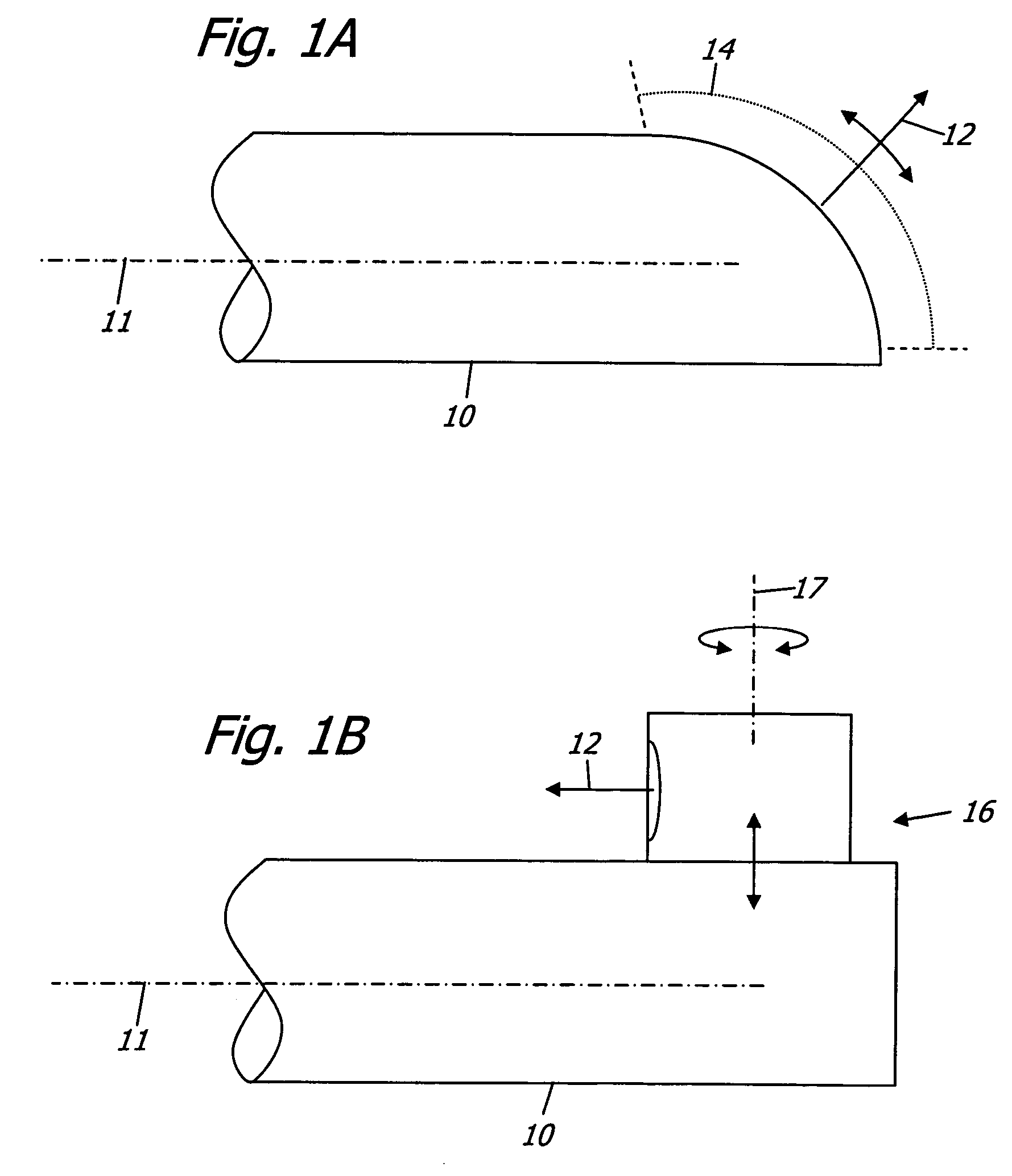
While this mechanism, rotatable about an axis 17 transverse to the longitudinal axis 11, is capable of looking directly backwards, it is not practical because of its complexity and it also has significant sealing problems.
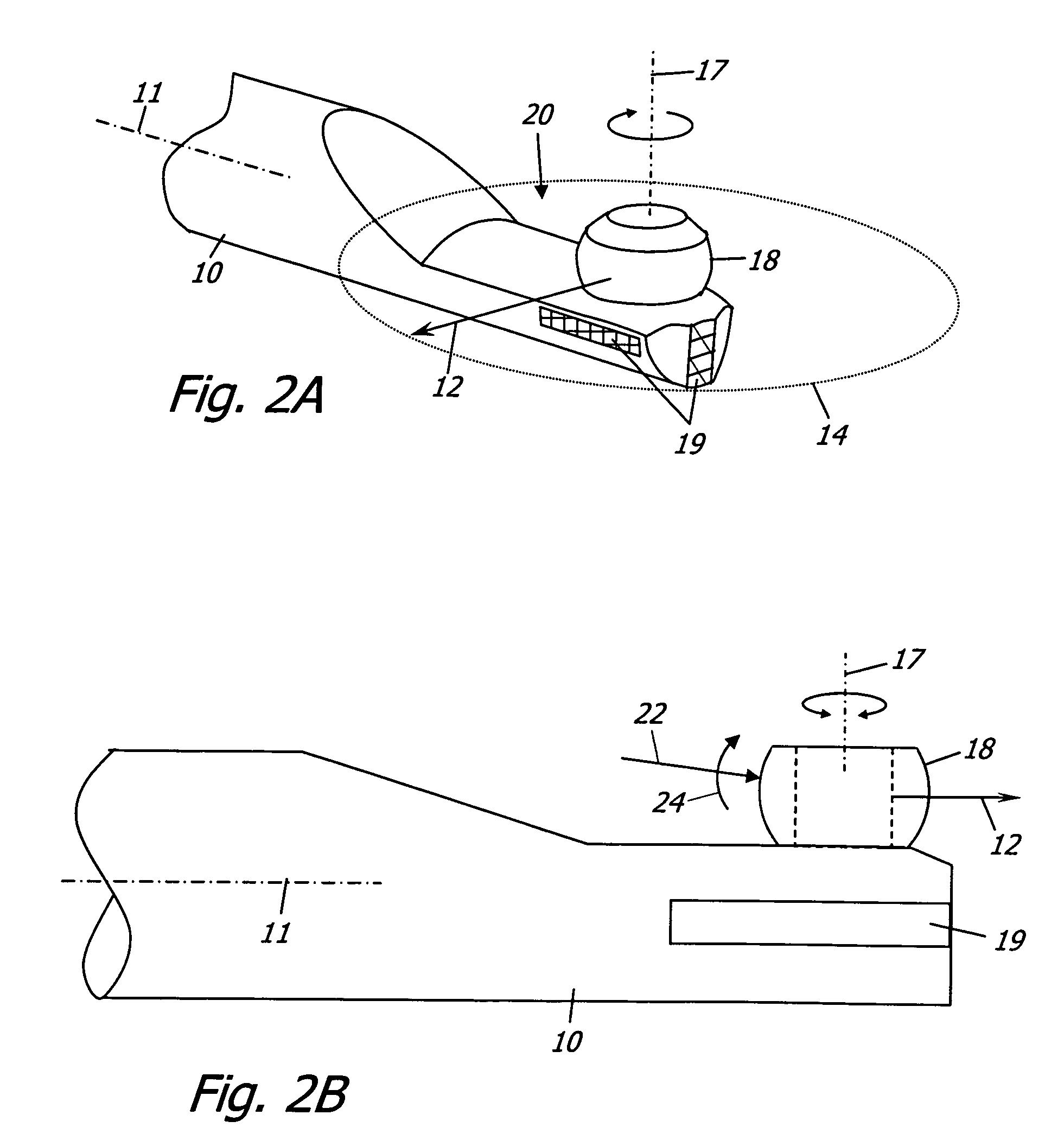
A weakness with this design is that the viewing window 18 is not shielded and is therefore more readily damaged.
Another problem, shown in FIG. 2B, is that environmental forces 22 cause moments 24 which tend to pry the viewing window 18 lose from the tip structure 10.
Method used
Image
Click on the blue label to locate the original text in one second.
Reading with bidirectional positioning of images and text.
Examples
embodiment
Preferred Embodiment
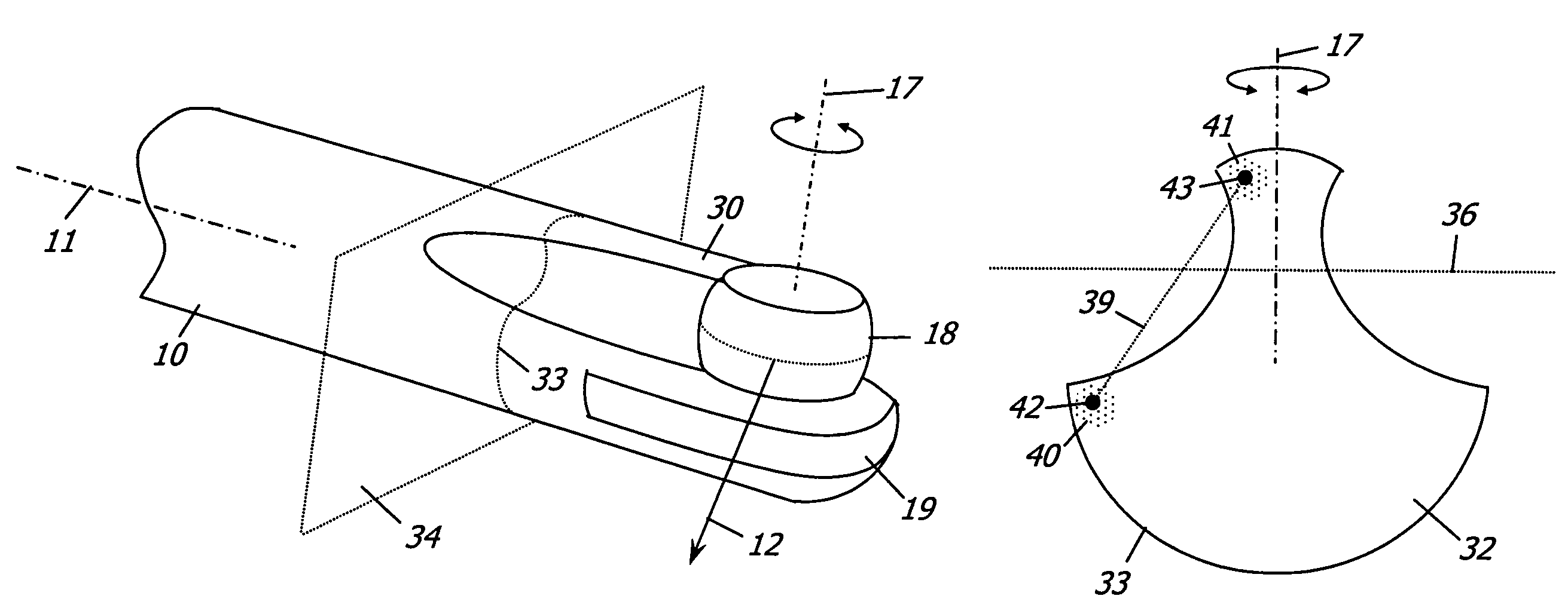
[0016]In the embodiment shown in FIG. 3A, the recessed section of FIG. 2A includes a ridge 30 which extends forward to the viewing window 18. There are three specific advantages with this tip design over the prior art: i) the ridge 30 prevents the viewing window 18 from getting snagged because it deflects environmental forces from the back which would otherwise stress and torque the viewing window 18; ii) the ridge 30 provides additional support for the viewing window 18 to withstand frontal and lateral forces; and iii) it still allows extreme retrospective viewing. A cross section 32 of this design, delimited by a boundary 33, and generated by a slice plane 34, is shown in FIG. 3B, along with the view vector scan plane 36 and the view vector pivot axis 17. The cross section 32 is defined to be the closed connected set of all points contained within and on the boundary 33. A region of this section 32 is defined as the neighborhood of points within the section 32 ...
PUM
Abstract
A variable direction of view endoscope generally comprising an endoscope shaft, an objective optical system disposed in the distal end of the shaft that defines a view vector movable relative to the longitudinal axis of the shaft, and a viewing window located in the distal end of the shaft through which the view vector scans over a range of different view vector directions when moved relative to the longitudinal axis of the shaft. A portion of the distal section of the endoscope shaft adjacent and proximal to the viewing window has a cross-section perpendicular to the longitudinal axis of the shaft, and at least two regions within the cross section are connectable by a straight line that does not lie within or on the boundary of the cross section. In certain embodiments, cross section comprises at least two disjoint closed sets of points.
Description
CROSS-REFERENCE TO RELATED APPLICATIONS[0001]This application claims the benefit of U.S. provisional application Ser. No. 60 / 556,603 filed on Mar. 26, 2004, entitled “Tip structure for a variable direction of view endoscope”, the contents of which are incorporated herein by reference.FIELD OF THE INVENTION[0002]The present invention relates to variable direction of view endoscopes.BACKGROUND OF THE INVENTION[0003]One of the shortcomings with rigid variable direction of view endoscopes, as disclosed in U.S. Pat. No. 3,856,000 to Chikama, U.S. Pat. No. 6,371,909 to Hoeg, U.S. Pat. No. 6,560,013 to Ramsbottom, U.S. Pat. No. 4,697,577 to Forkner, U.S. Pat. No. 6,500,115 to Krattiger et al., and U.S. Pat. No. 5,762,603 to Thompson, U.S. Pat. No. 5,313,306 to Kuban, and U.S. Pat. No. 5,800,341 to McKenna et al., is their limited retrospective viewing ability. Retrospective viewing would be important in industrial or medical diagnoses because mechanical cracks or tumors sometimes develop i...
Claims
Application Information
Patent Timeline
Application Date:The date an application was filed.
Publication Date:The date a patent or application was officially published.
First Publication Date:The earliest publication date of a patent with the same application number.
Issue Date:Publication date of the patent grant document.
PCT Entry Date:The Entry date of PCT National Phase.
Estimated Expiry Date:The statutory expiry date of a patent right according to the Patent Law, and it is the longest term of protection that the patent right can achieve without the termination of the patent right due to other reasons(Term extension factor has been taken into account ).
Invalid Date:Actual expiry date is based on effective date or publication date of legal transaction data of invalid patent.
Patent Type & AuthorityPatents(United States)
IPC IPC(8): A61B1/00
CPCA61B1/00183
InventorHOEG, HANS DAVIDSCHARA, NATHAN JONHALE, ERIC LAWRENCE

