

Zoom lens and image pickup apparatus including the same
- Summary
- Abstract
- Description
- Claims
- Application Information
AI Technical Summary
Benefits of technology
Problems solved by technology
Method used
Image

Examples
first embodiment
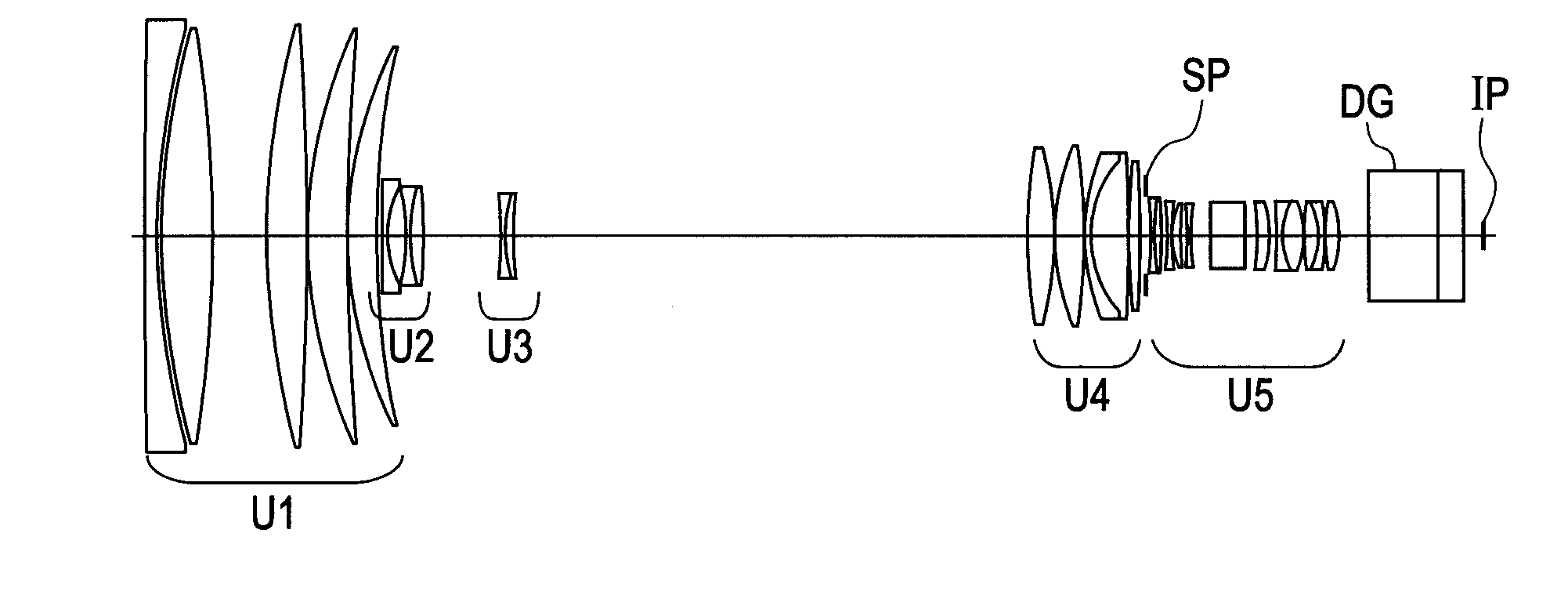
[0076]A description is made of the second lens unit U2, the third lens unit U3 and the fourth lens unit U4 in the zoom lens according to the first embodiment corresponding to Numerical Embodiment 1. These lens units are movable lens units that move during zooming. The second lens unit U2 includes the 11th to 15th lens surfaces in Numerical Embodiment 1 and is composed, in order from the object side to the image side, of a negative lens and a cemented lens made up of a negative lens and a positive lens that are arranged in this order and cemented together. The third lens unit U3 includes the 16th to 18th lens surfaces in Numerical Embodiment 1 and is composed of a cemented lens made up of a negative lens and a positive lens that are arranged in this order and cemented together.
[0077]The fourth lens unit U4 includes the 19th to 27th lens surfaces in Numerical Embodiment 1 and is composed, in order from the object side to the image side, of two positive lenses, a cemented lens made up ...
second embodiment
[0079]The zoom lens according to the second embodiment corresponding to Numerical Embodiment 2 has the same lens configuration as the first embodiment and satisfies all the conditional expressions as seen from Table 1 to have excellent optical performance. The zoom lens according to this embodiment is small in size and light in weight with a diameter of the lens on the most object side in the first lens unit U1 of 212.59 mm while having a wide angle of view with a focal length of 8.5 mm at the wide-angle end and a high zoom ratio of 100.
third embodiment
[0080]The zoom lens according to the third embodiment corresponding to Numerical Embodiment 3 has the same lens configuration as the first embodiment and satisfies all the conditional expressions as seen from Table 1 to have excellent optical performance. The zoom lens according to this embodiment is small in size and light in weight with a diameter of the lens on the most object side in the first lens unit U1 of 210.28 mm while having a wide angle of view with a focal length of 8.4 mm at the wide-angle end and a high zoom ratio of 80.
PUM
 Abstract
Description
Claims
Application Information