Viewing optical system, and imaging apparatus comprising the same

a technology of optical system and optical lens, applied in the field of viewing optical system, can solve the problems of increasing the image size of the focusing screen, and unsuitable for reducing the size of the prism, and achieve the effect of easy reducing the viewing angle of field

Inactive Publication Date: 2009-04-16
OM DIGITAL SOLUTIONS CORP
View PDF1 Cites 12 Cited by
  • Summary
  • Abstract
  • Description
  • Claims
  • Application Information

AI Technical Summary

Benefits of technology

[0023]As the refractive index of the prism grows high in such a way as to satisfy condition (1), it facilitates making sure an optical path even when the focal length of the eyepiece lens system is curtailed. And to make the prism much smaller while making sure the field of view, it is preferable to curtail the focal length of the eyepiece lens system in such a way as to satisfy condition (2), thereby taking hold of the field of view. To, in that case, make sure the field of view and layout and take hold of optical performance, it is preferable to tweak the arrangement of the eyepiece lens system, thereby facilitating making sure the field of view while placing the principle points closer to the screen.
[0074]According to the invention, it is possible to obtain a viewing optical system that, albeit being of small size, can view subjects over a wide field of view by tweaking the eyepiece lens system while taking advantage of the merit of making sure the optical path length by use of a prism having a high refractive index.

Problems solved by technology

However, the eyepiece lens system of the viewing optical system set forth in each patent publication has a longer focal length, and when it is intended to obtain a viewing image having a wide field of view, there is no option but to increase image size on a focusing screen: it is unsuitable for diminishing prism size.
However, imaging plane size is smaller than that of a conventional Leica size film: when the aforesaid viewing optical system is used, the viewing angle of field tends to become small.

Method used


Image

  • Viewing optical system, and imaging apparatus comprising the same
  • Viewing optical system, and imaging apparatus comprising the same
  • Viewing optical system, and imaging apparatus comprising the same

Examples


Embodiment Construction

[0082]Some examples of the invention are now explained with reference to the drawings.

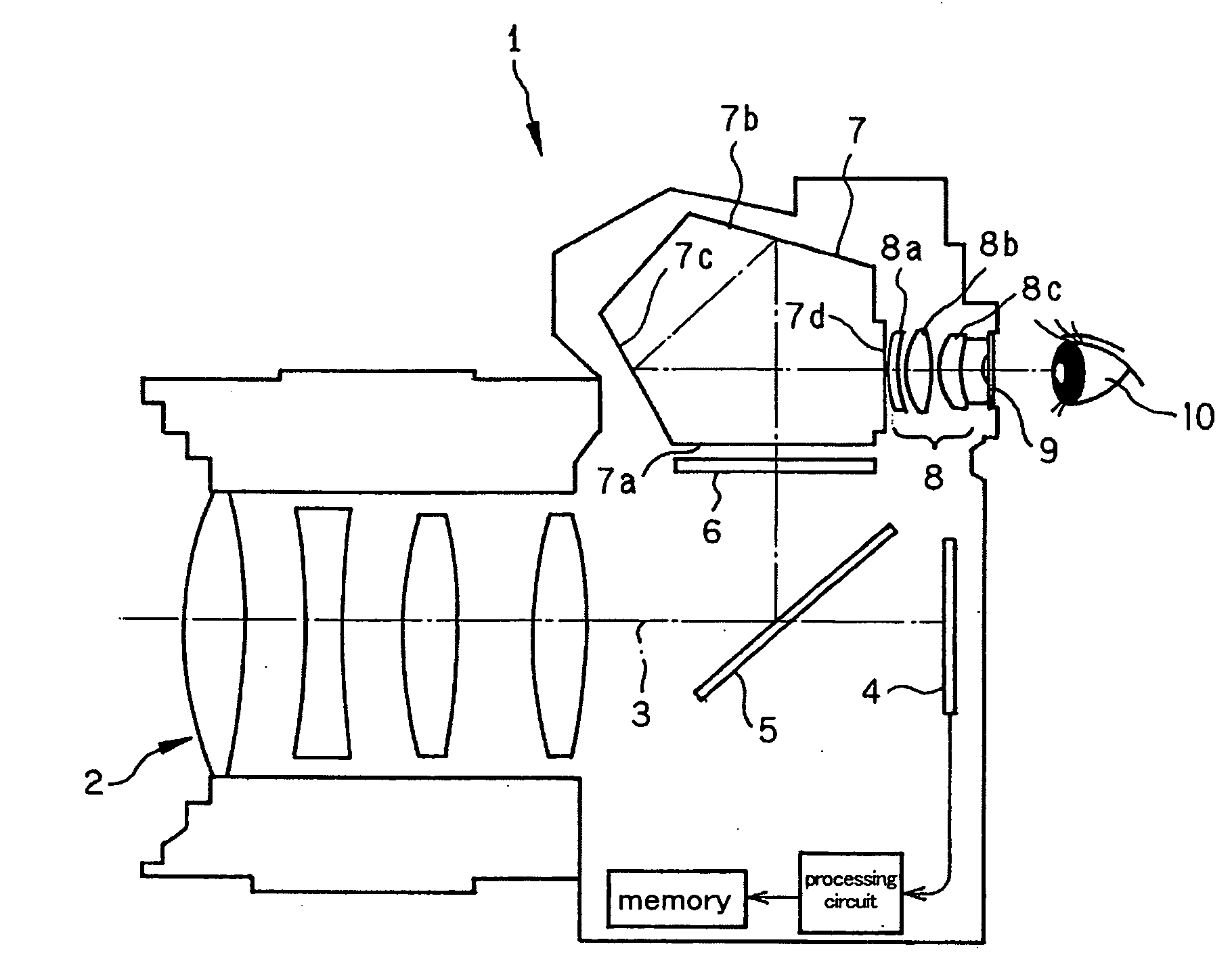
[0083]FIG. 1 is illustrative in schematic, common to the respective examples, of the arrangement of one embodiment of a single-lens reflex camera comprising the inventive viewing optical system.

[0084]In a single-lens reflex camera 1 of FIG. 1, a taking lens 2 is interchangeably attached to the camera by a mount (not shown). Note here that even an arrangement that does not include a taking lens is herein defined as a single-lens reflex camera (imaging apparatus) provided that the taking lens is attachable to it.

[0085]In FIG. 1, reference numeral 4 is a CCD (or CMOS or the like). On the basis of signals from this CCD, image processing is implemented at a processing circuit to store image information in a memory. The stored image may be displayed on a personal computer (not shown) or the like, or it may be recorded and stored in various storage media.

[0086]Reference numeral 5 is a quick return mirror ...


PUM


Abstract

The invention relates to a viewing optical system for viewing an object image formed on a focusing screen, and an imaging apparatus comprising the same. An image erection optical system comprises a prism having an internal reflective surface. An eyepiece optical system comprises, in order from a screen side to an exit pupil side, a first lens component having negative refracting power wherein its exit pupil-side surface has a paraxial-radius-of-curvature absolute value smaller than that of its screen-side surface, a second lens component in a double-convex shape and a third meniscus lens component in a meniscus shape concave on an exit pupil side. The total number of lens components included in the eyepiece optical system is 3, and the following conditions (1), (2) and (3) are satisfied.1.55<ndp   (1)0.35<fe / Dip<0.60   (2)1.0<D3 / (D1+D2)<1.8   (3)

Description

[0001]This application claims benefit of Japanese Patent Application No. 2007-263971 filed in Japan on Oct. 10, 2007, the contents of which are incorporated by this reference.BACKGROUND OF THE INVENTION[0002]The present invention relates to a viewing optical system for viewing an object image formed on a focusing screen, and an imaging apparatus comprising the same.[0003]So far, a single-lens reflex camera used as an imaging apparatus making use of a film or electronic imaging device has comprised an image erection optical system such as a penta roof prism and an eyepiece lens system adapted to guide a light beam leaving that image erection optical system to the eyeball of a viewer for the purpose of viewing an object image on a focusing screen onto which a subject image is projected via a taking lens.[0004]Such viewing optical systems include those designed to make the refractive index of a prism material so high that an optical path for the image erection function of the prism is ...

Claims


Application Information

Patent Timeline
Patent Type & Authority Applications(United States)
IPC IPC(8): G02B17/08G02B27/02G02B17/04
CPCG02B25/001G02B13/04
Inventor YOKOYAMA, KEITARO
Owner OM DIGITAL SOLUTIONS CORP
Why Eureka
Try Eureka