Water resistant in-line fuse holder

a fuse holder and water-resistant technology, applied in the direction of electrical equipment, emergency protection devices, coupling device connections, etc., can solve the problems of poor electrical connection, corroding of the effectiveness of the fuse element, poor water resistance, etc., to improve the water resistance of the fuse holder and the in-line fuse holder

Active Publication Date: 2008-05-27
LITTELFUSE INC
View PDF32 Cites 13 Cited by
  • Summary
  • Abstract
  • Description
  • Claims
  • Application Information

AI Technical Summary

Benefits of technology

[0027]It is therefore an advantage of the present invention to provide an improved in-line fuse holder.
[0028]It is another advantage of the present invention to provide an improved water resistant fuse holder.
[0029]It is a further advantage of the present invention to provide multiple embodiments for an in-line and / or water resistant fuse holder.
[0030]Moreover, it is an advantage of the present invention to provide in-line and / or water resistant fuse holders that are operable with different types of fuses, such as typical blade fuses, low profile blade fuses and cartridge fuses.
[0031]Additional features and advantages of the present invention are described in, and will be apparent from, the following

Problems solved by technology

With any type of blade fuse, moisture inadvertently contacting any conductive part of the plug-in fuse can cause problems.
In an extreme situation, the moisture can extend across the terminals causing a second current path, which can negate the effectiveness of the element.
Alternatively or additionally, the moisture can cause the terminals and / or the fuse element and corresponding female terminals to corrode.
Corrosion of the male and female terminals can lead to a poor electrical connection and / or a connection between the male and female terminals that is difficult to disassemble.
Existing water resistant fuse holders are relatively expensive.
Further, no such holder exists for the “low profile” blades fuses described above.

Method used


Image

  • Water resistant in-line fuse holder
  • Water resistant in-line fuse holder
  • Water resistant in-line fuse holder

Examples


Embodiment Construction

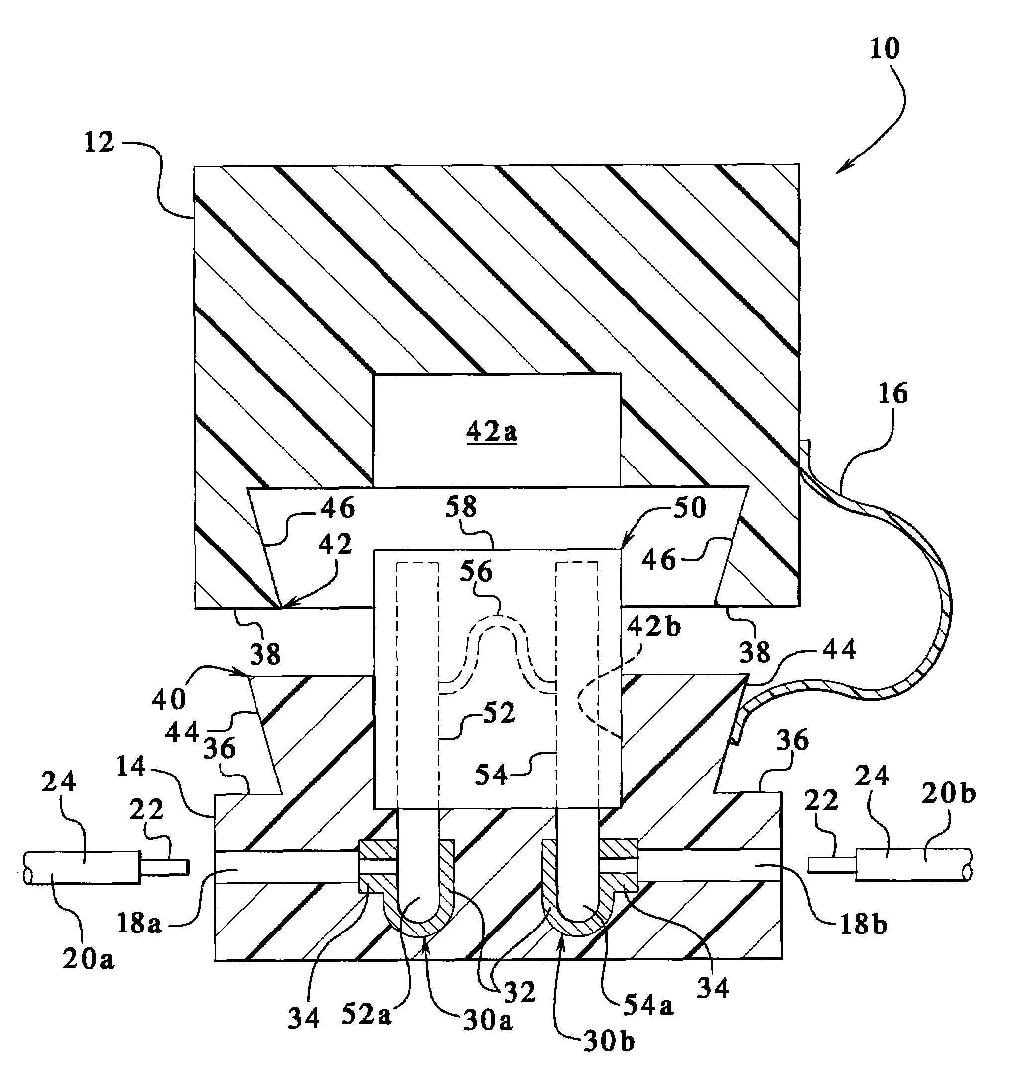
[0047]Referring now to the drawings and in particular to FIG. 1, one example of an in-line and / or water resistant fuse holder is illustrated by fuse holder 10. Fuse holder 10 includes an upper housing 12 and a lower housing 14. Housings 12 and 14 are connected removably together by a strap 16. Housing 12, housing 14 and strap 16 may be made of any suitable one or more material, such as plastic, rubber, etc., or any combination thereof. Housing 12 may be made of the same or different material as is housing 14. In an embodiment, housings 12 and 14 are molded pieces, such as pieces made via injection molding, blow molding, etc., or any combination thereof. Housings 12 and 14 may be made as a single piece construction with strap 16. Alternatively, housings 12 and 14 are made separately, and strap 16 is formed integrally with one of the housings and (i) bonded, (ii) heat-sealed, (iii) sonically sealed or (iv) adhered to the other of the housings. Strap 16 is further alternatively fixed v...


PUM


Abstract

Embodiments for an in-line fuse holder each include at least one housing and two mating pieces, which can snap-fit together and be held moveably together via a strap. Each embodiment houses at least one fuse, such as an automotive fuse. In one example, the fuse includes a first housing forming a first cavity, which is configured to house a first portion of the fuse. The first housing also includes a projection having sides that taper outwardly as the sides extend away from the first housing. The fuse holder also includes a second housing forming a second cavity, which is configured to house a second portion of the fuse. The second housing includes a channel having sides that taper outwardly as the sides extend into the second housing. The projection and channel snap-fit together in a water resistant relationship.

Description

PRIORITY CLAIM[0001]This application claims the benefit of U.S. Provisional Patent Application No. 60 / 692,179, filed Jun. 20, 2005, entitled, “WATER RESISTANT IN-LINE FUSE” and U.S. Provisional Patent Application No. 60 / 741,987, filed Dec. 2, 2005, entitled, “WATER RESISTANT IN-LINE FUSE HOLDER,” the entire contents of each of which are hereby incorporated by reference and relied upon.BACKGROUND OF THE INVENTION[0002]The present invention relates generally to overcurrent protection.[0003]Plug-in type fuses, such as blade fuses, generally include a fuse link in electrical communication with a pair of terminals. The fuse element and terminals are housed in a plastic fuse body. The terminals extend out of the housing, so that the fuse may be mounted into a fuse block of an automobile. Such blade type fuses have become very popular, especially in automotive applications.[0004]Recently, “low profile” blade fuses have been introduced. One such “low profile” blade fuse is described in U.S....

Claims


Application Information

Patent Timeline
Patent Type & Authority Patents(United States)
IPC IPC(8): H01R13/68
CPCH01H85/2015H01H85/2035H01R13/5202H01R13/68H01H9/04
Inventor PENTELL, CHRISTIANADAMCZYK, JOHNKLINGER, CHARLES E.
Owner LITTELFUSE INC
Why Eureka
Try Eureka