
Mechanical cushioning system for footwear

a cushioning system and footwear technology, applied in the direction of shoes, top-pieces, heels, etc., can solve the problems of the useful life of foam materials such as the eva foam commonly used in the midsole is limited, and the goal is potentially in conflict with each other, so as to maximize comfort and durability

Active Publication Date: 2008-06-10
NEW BALANCE ATHLETIC SHOE INC
View PDF18 Cites 132 Cited by
  • Summary
  • Abstract
  • Description
  • Claims
  • Application Information

AI Technical Summary

Benefits of technology

[0015]In view of the foregoing, it is an object of the present invention to provide an athletic shoe that optimizes the conflicting concerns of shock absorption and stability, while also maximizing comfort and durability.
[0016]It is a more specific object of the present invention to construct an athletic shoe having a sole unit which provides differential cushioning properties at different regions of the sole, so as to attenuate impact forces at heel strike without introducing instability to the subsequent motion in the running gait cycle.
[0017]It is another object of the present invention to provide an athletic shoe sole that adopts a mechanical cushioning system, which is designed to absorb impact forces with a specific configuration of an elastic and durable material, eliminating the need for relying heavily on the less durable foam material for impact absorption.
[0018]It is a further object of the present invention to provide an athletic shoe sole having a mechanical cushioning system which can be easily customized for the specific application and individual wearing the shoe by slightly modifying its configuration.
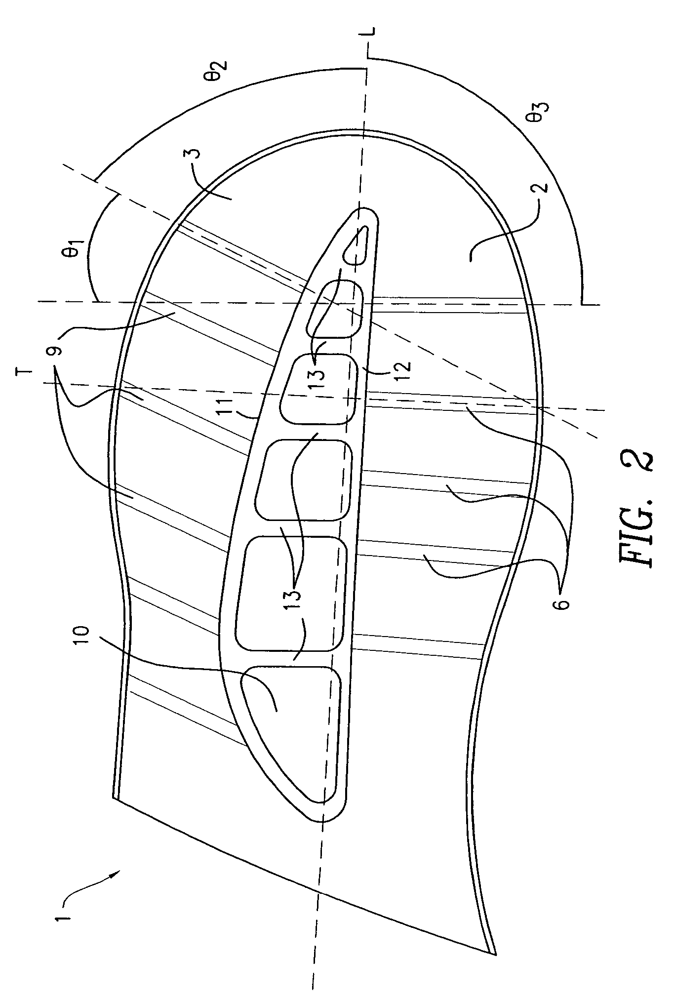
[0022]In accordance with a further aspect of the present invention, the midsole element described above further comprises a heel cleft which is medial to the point of heel strike at the midsole element. The heel cleft provides flexibility to the midsole and allows the midsole to bend at impact thereby decreasing the amount and velocity of pronation. The heel cleft is about 0 to about 180 degrees, preferably about 0 to about 120 degrees, more preferably about 0 to about 90 degrees, offset from the transverse axis of the midsole. For shoes intended for linear movement activities such as walking and running, the heel cleft is preferably about 15 to about 75 degrees, and more preferably about 17 and about 65 degrees, offset from the transverse axis of the midsole. For shoes intended for lateral movement activities such as basketball, the heel cleft may be about 65 to about 90 degrees, preferably about 75 to about 90 degrees, offset from the transverse axis of the midsole.

Problems solved by technology

Unfortunately, these goals are potentially in conflict with each other.
For example, a shoe that provides adequate shock absorption and comfort may not provide sufficient stability.
Foam materials such as the EVA foam commonly used in the midsole have limited useful lives and tend to break down over time.
The prior art soles described above do not provide the shoes with optimal shock absorption and stability due to their design.

Method used


Image

  • Mechanical cushioning system for footwear
  • Mechanical cushioning system for footwear
  • Mechanical cushioning system for footwear

Examples


Embodiment Construction

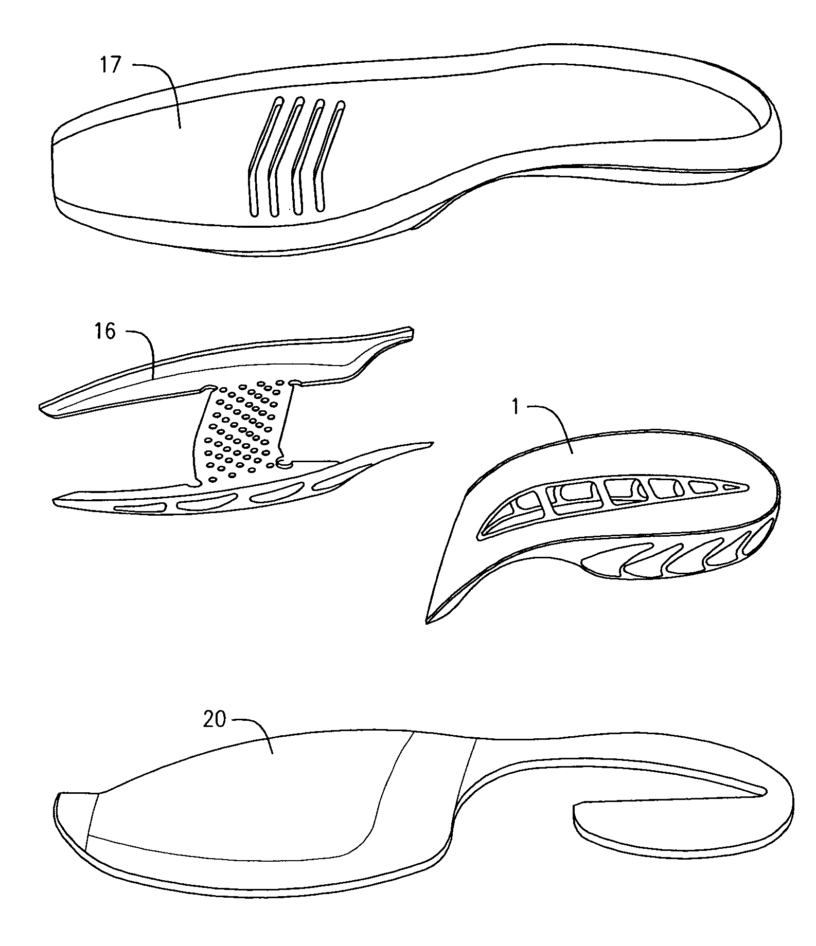
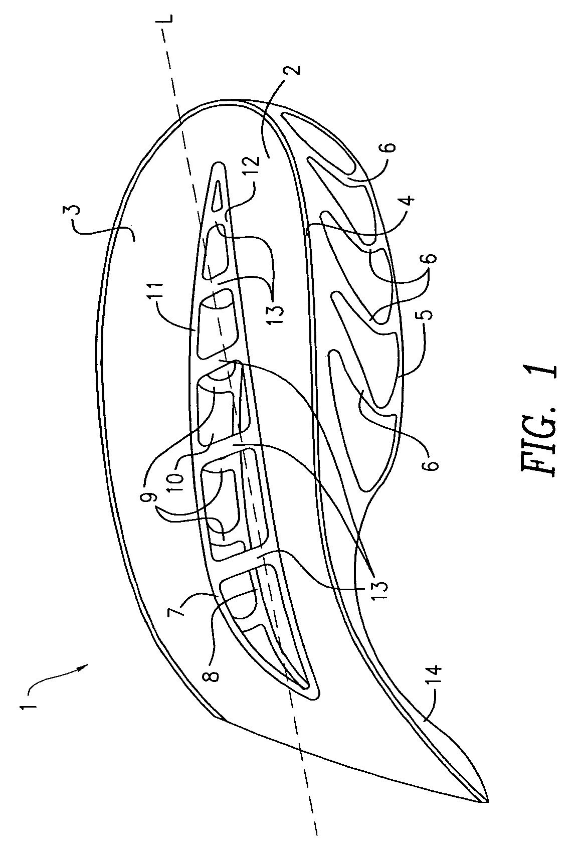
[0043]The present invention can be better understood from the following description of preferred embodiments, taken in conjunction with the accompanying drawings. It should be apparent to those skilled in the art that the described embodiments of the present invention provided herein are merely exemplary and illustrative and not limiting. All features disclosed in the description may be replaced by alternative features serving the same or similar purpose, unless expressly stated otherwise. Therefore, numerous other embodiments of the modifications thereof are contemplated as falling within the scope of the present invention and equivalents thereto.

[0044]FIGS. 1 and 2 illustrate an exemplary embodiment of a midsole element in accordance with one aspect of the present invention. The midsole element 1 comprises: a medial element 2 and a lateral element 3. The medial element comprises a top medial plate 4, a bottom medial plate 5, and a plurality of medial strut members 6 disposed betwe...


PUM


Abstract

A midsole for footwear comprising a midsole element, which comprises a top plate, a bottom plate, and a plurality of strut members disposed between the top and bottom plates for supporting the top plate a distance away from the bottom plate. Adjacent strut members have a C shaped cross-section facing in the same direction. The midsole element may further comprise a heel cleft to increase the flexibility of the sole. In a preferred embodiment, the strut members on the medial side are arranged at an angle to the strut members on the lateral side of the sole. The directional design provides flexibility and stiffness anisotropically to the sole in the longitudinal and lateral directions of the sole respectively.

Description

BACKGROUND OF THE INVENTION[0001]Footwear, in particular athletic footwear, are expected to provide proper shock absorption and stability thereby preventing potential harmful effects of vigorous movements such as running and jumping on the wear's feet. The footwear industry has been developing athletic shoes in an effort to maximize shock absorption and stability while also maximizing comfort and durability. Unfortunately, these goals are potentially in conflict with each other. For example, a shoe that provides adequate shock absorption and comfort may not provide sufficient stability. To further advance the development of athletic shoes, a basic understanding of the dynamics of running and the mechanisms of running injuries is important.[0002]A typical walking or running gait cycle involves two phases: (1) a stance phase, and (2) a swing phase. One foot contacts the support surface such as the ground and bears weight in the stance phase while the other foot is moving through the a...

Claims


Application Information

Patent Timeline
Patent Type & Authority Patents(United States)
IPC IPC(8): A43B13/18
CPCA43B7/142A43B13/141A43B13/16A43B13/186A43B21/26A43B21/32
Inventor CHAN, MARYA L.CHOE, PATRICK Y.DIRSA, DAVID J.HARMON-WEISS, EDITHMURPHY, SEAN B.
Owner NEW BALANCE ATHLETIC SHOE INC
Learn More