Sheet handling device for wide format sheets

a technology for handling devices and sheets, applied in the direction of printing, pile separation, printers, etc., can solve the problems of affecting the advance of the sheet over the support element, the sheet is not held firmly on the support element, and the suction is too strong, so as to save space. the effect of construction

Inactive Publication Date: 2008-06-10
OCE TECH
View PDF17 Cites 8 Cited by
  • Summary
  • Abstract
  • Description
  • Claims
  • Application Information

AI Technical Summary

Benefits of technology

[0005]It is an object of the present invention to provide a sheet handling device in which sheets of different sizes can be held down on a sheet support element with appropriate suction pressure, the sheet handling device being of simple and space saving construction.
[0007]The flow restricting orifices restrict the air flow from a compartment that is not covered by a sheet. Thus, the necessary subatmospheric pressure can be maintained in those compartments that are covered by the sheet. When, however, a sheet of larger size covers also the suction holes for which the flow path is restricted by the orifices, the flow rate will be reduced substantially. Thus, the effect of the flow resistance of the orifices will also be reduced, and the suction effect will be essentially uniform over the whole area of the sheet. Furthermore, no extra space is needed for bypass channels and the like. Another advantage is that the size of the compartments can be chosen by arranging the internal walls at appropriate positions in the suction chamber. Therefore, when manufacturing the sheet handling device, the sheet support place is readily adaptable to the required sizes of the compartments. Furthermore, since the internal walls do not require extra space outside of the suction chamber, the number of compartments may easily be increased. Therefore, the sheet handling device can readily be adapted to handle sheets of more than two sizes.
[0008]Preferably, the compartments are arranged symmetrically. Thus, the maximum distance of a compartment from the suction means is reduced as compared to, e.g., a configuration in which the suction device is connected to a first compartment in a chain of interconnected compartments. With this preferred arrangement, smaller sheets may be passed over the first compartment in a middle section of the sheet support plate instead of being fed at a lateral edge of the sheet support plate.
[0009]In a preferred embodiment, at least two groups of compartments are arranged in the direction of advance of the sheet, and only one group has a compartment that is directly connected to the suction device, whereas the compartments of the other group or groups are connected indirectly through flow restricting orifices. This helps to reduce the air flow into the suction chamber when a sheet covers only part of the support plate in the transport direction of the sheet. For example, when a new sheet is printed and advanced onto the sheet support plate, the sheet may already cover a compartment of the first group while the leading edge of the sheet has not yet reached a neighboring compartment of the second group.

Problems solved by technology

This results in the sheet not being held firmly on the support element.
If, on the other hand, a suction device of higher power is used to compensate for the increased air flow into the suction chamber, the suction will be too strong when all suction holes are covered by a large sheet, and the advance of the sheet over the support element is impeded.
However, only a limited number of different sheet widths can be handled.
Furthermore, for each partition of the support plate an extra bypass channel is needed and requires extra space.

Method used


Image

  • Sheet handling device for wide format sheets
  • Sheet handling device for wide format sheets
  • Sheet handling device for wide format sheets

Examples


Embodiment Construction

[0011]Preferred embodiments of the present invention will now be described in conjunction with the drawings, in which:

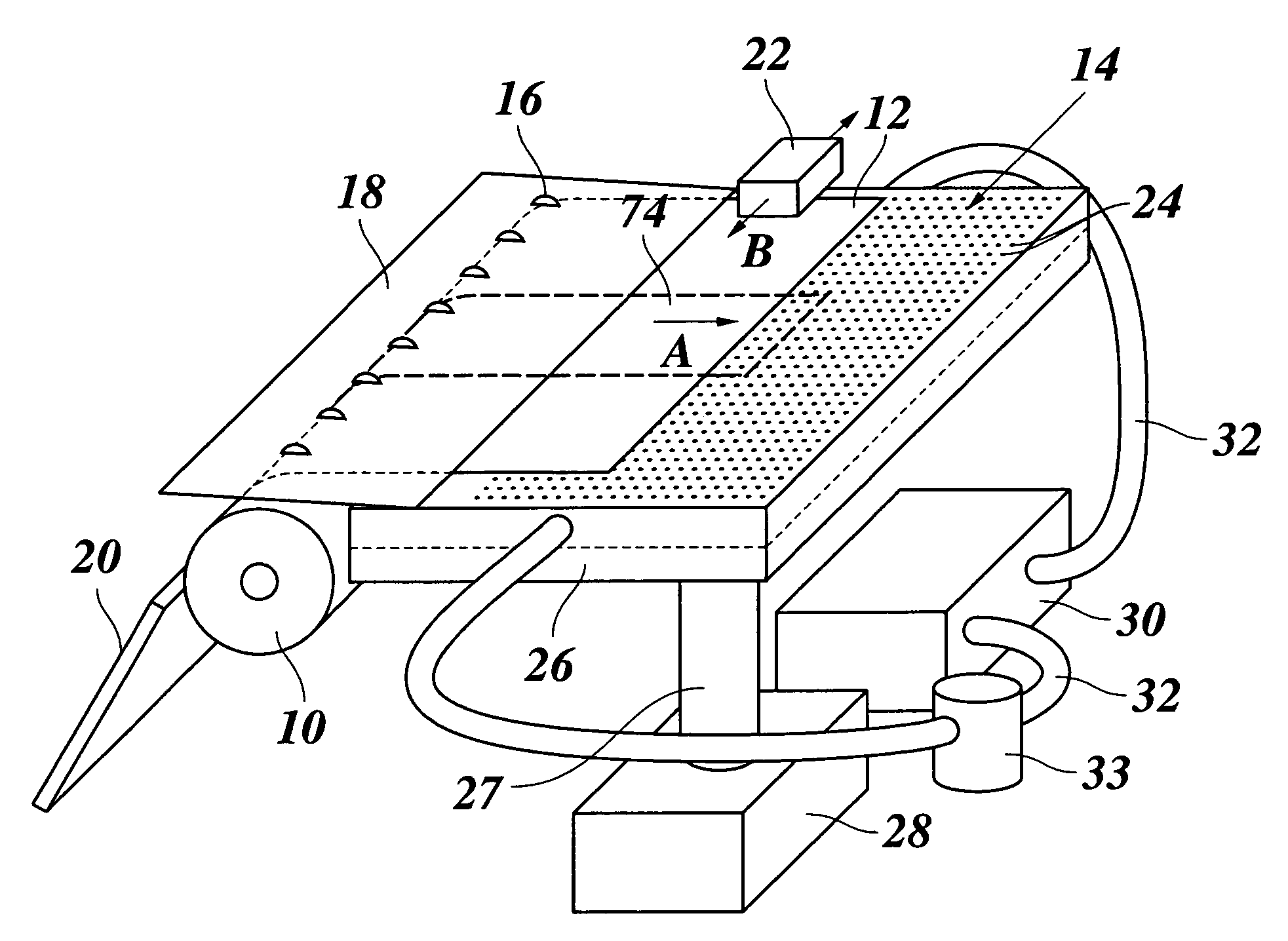
[0012]FIG. 1 is a schematic perspective view of a hot-melt ink jet printer;

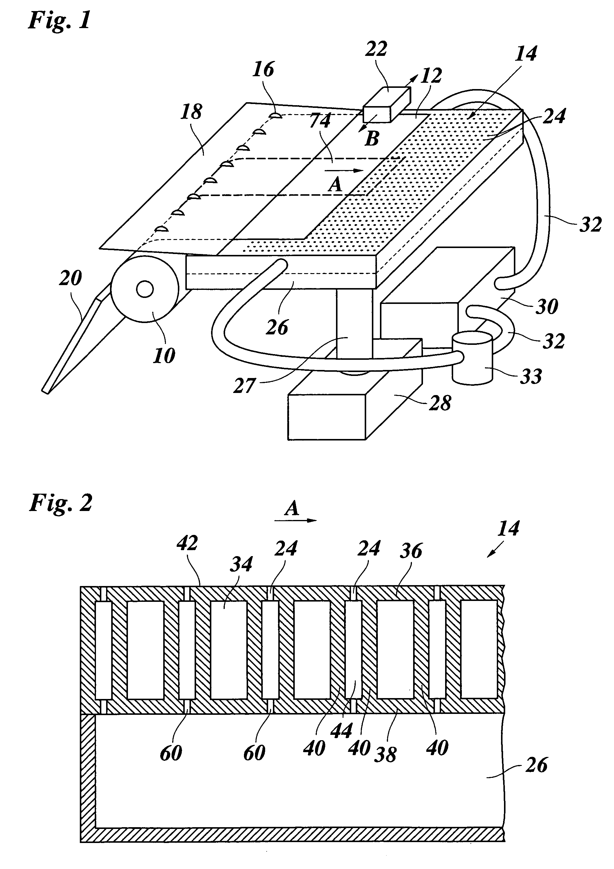
[0013]FIG. 2 is a partial cross section of a sheet support plate in the printer shown in FIG. 1;

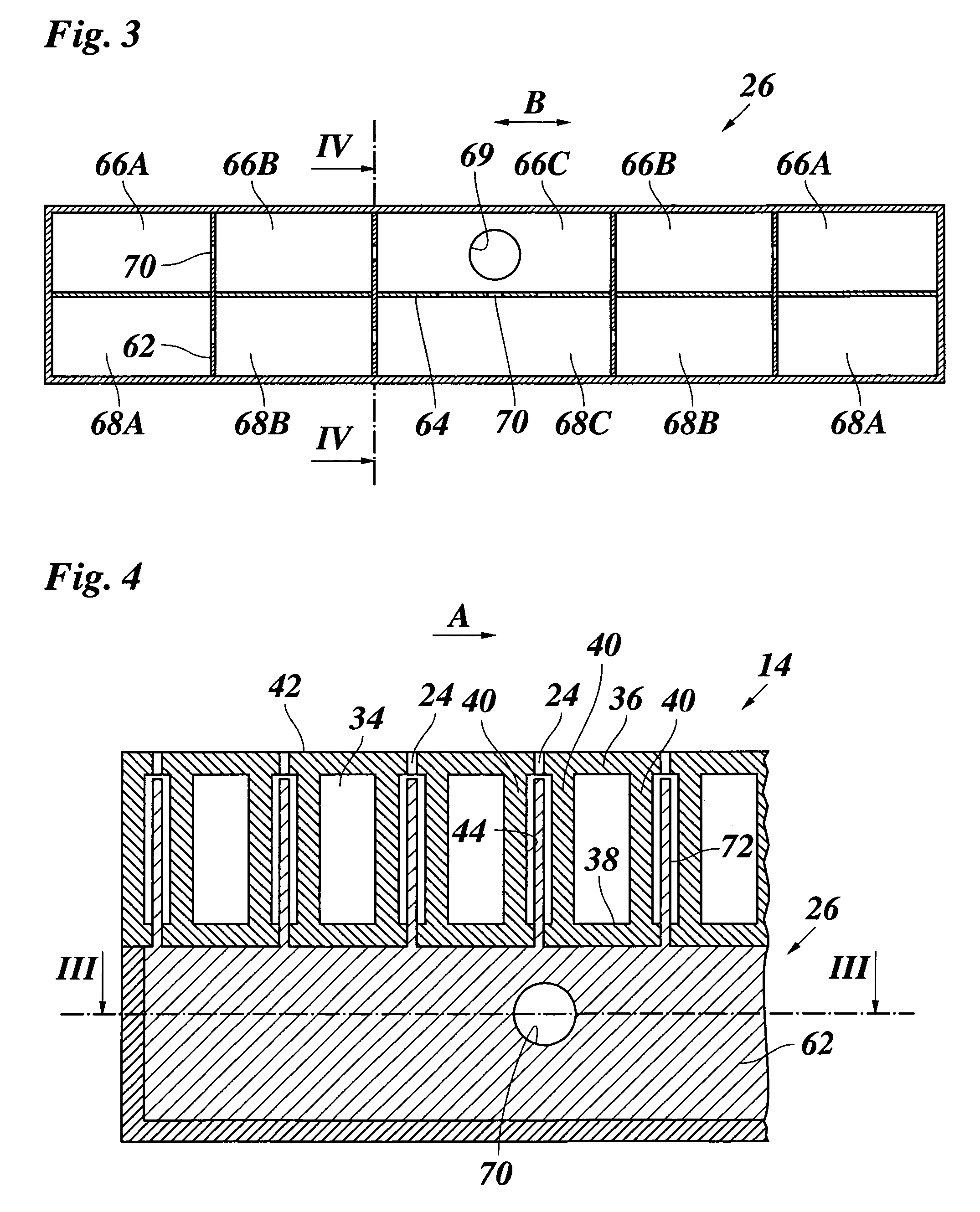
[0014]FIG. 3 is an enlarged section of a suction chamber of the sheet support plate, the section being taken along the line III-III in FIG. 4;

[0015]FIG. 4 is a partial cross section along the line IV-IV in FIG. 3; and

[0016]FIG. 5 is a partial cross section of a modified embodiment of the sheet support plate.

DETAILED DESCRIPTION OF THE INVENTION

[0017]As is shown in FIG. 1, a hot melt ink jet printer includes a platen 10 which is intermittently driven to rotate in order to advance a sheet 12, e. g. a sheet of paper, in a direction indicated by an arrow A over the top surface of a sheet support plate 14. A number of transport rollers 16 are rotatably supported in a cover plate 18 and form a transport n...


PUM


Abstract

A sheet handling device for wide format sheets including a sheet support plate having a top surface containing suction holes which are connected to at least one suction chamber, the at least one suction chamber being divided into compartments that are connected, though an opening, to a suction device adapted to create a subatmospheric pressure in the compartments, wherein at least one internal wall between adjacent ones of the compartments defines a flow restriction orifice, and at least one of the compartments is directly connected to the suction device, and at least another one of the compartments is indirectly connected to the suction device through the orifice.

Description

BACKGROUND OF THE INVENTION[0001]The present invention relates to a sheet handling device for wide format sheets including a sheet support plate, said plate having a top surface containing suction holes which are connected to at least one suction chamber, said at least one suction chamber being divided into compartments that are connected to a suction device adapted to create a subatmospheric pressure in the compartments.[0002]In the copying and printing industry, a sheet support element with suction holes is frequently used for supporting an image receiving sheet and at the same time ensuring that the sheet lies perfectly flat on the support element. For example, in an ink jet printer, a sheet, e.g. a sheet of paper, is advanced over a sheet support plate while the image is being printed. The sheet is held on the sheet support plate due to the subatmospheric pressure in the suction chamber which is connected to suction holes facing the bottom side of the sheet. A certain subatmosph...

Claims


Application Information

Patent Timeline
Patent Type & Authority Patents(United States)
IPC IPC(8): B65H29/24B65H5/00B65H29/32
CPCB41J11/0085B41J11/06B65H2406/35B65H2406/3632B65H2701/11312
Inventor KRUIJT, PIETER G. M.
Owner OCE TECH
Why Eureka
Try Eureka