Gas Generator

a generator and gas technology, applied in the direction of pedestrian/occupant safety arrangement, transportation and packaging, vehicle safety arrangements, etc., to achieve the effect of improving the deflagration behavior of the propellant, simple design, and increasing the flow cross-section

Active Publication Date: 2008-12-04
TRW AIRBAG SYST
View PDF7 Cites 3 Cited by
  • Summary
  • Abstract
  • Description
  • Claims
  • Application Information

AI Technical Summary

Benefits of technology

[0004]This is achieved in a gas generator, in particular for a vehicle occupant restraint system, comprising a rigid outer housing, a chamber formed in the outer housing, in which a compressed gas is present at least upon activation of the gas generator, a component immovable, at least one outflow opening formed in the component immovable relative to the outer housing, and at least one substantially flat, resilient element, which is clamped inside the outer housing and rests against the immovable component at least in its normal position. In its normal position, the resilient element closes a flow path between the chamber and external surroundings of the gas generator and is deformed elastically under the influence of compressed gas, whereby it clears a flow cross-section whose size is increasing with increasing pressure. By means of the spring element, a variable flow cross-section and hence a variable outflow of the gas generator thus is achieved in dependence on the internal pressure. While comparatively little gas flows out in the case of a low internal pressure, a hi...

Problems solved by technology

However, the outflow cross-section influences the combustion chamber pressure and hence in turn the deflagration ...

Method used


Image

  • Gas Generator
  • Gas Generator
  • Gas Generator

Examples


third embodiment

[0045]FIG. 8 shows the gas generator 10 of the invention, which differs from the embodiments described so far in that the resilient element 26 has the shape of a spherical shell portion or a spherical cap. In its edge portion 33, the resilient element 26 rests against the end-face wall 28 of the diffuser portion 16 on the outer housing 12, whereas the middle portion closes the outflow opening 22 in the normal position shown in FIG. 8. Upon application of compressed gas, the flow cross-section 30 is formed between the edge of the outflow opening 22 and the resilient element 26, in that the same is slightly lifted.

[0046]The gas generator 10 as shown in FIG. 9 merely differs from the one of FIG. 8 in that the resilient element 26 is arranged rotated by 180°, i.e. supports on the end-face wall 28 in its central portion and on the closing element 20 in its edge portion 33. In this aspect, the flow cross-section 30 is formed on the outer edge of the closing element 20.

sixth embodiment

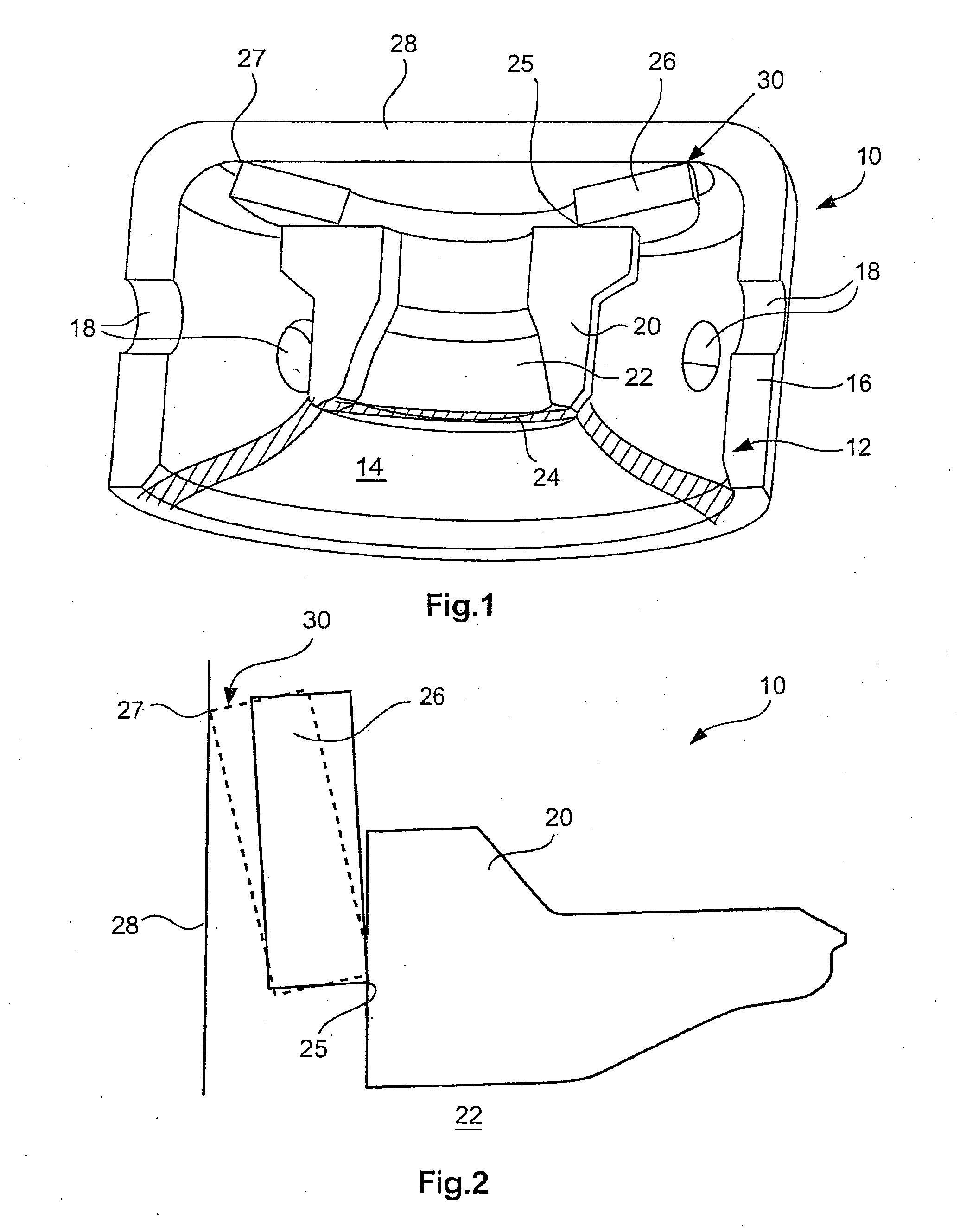
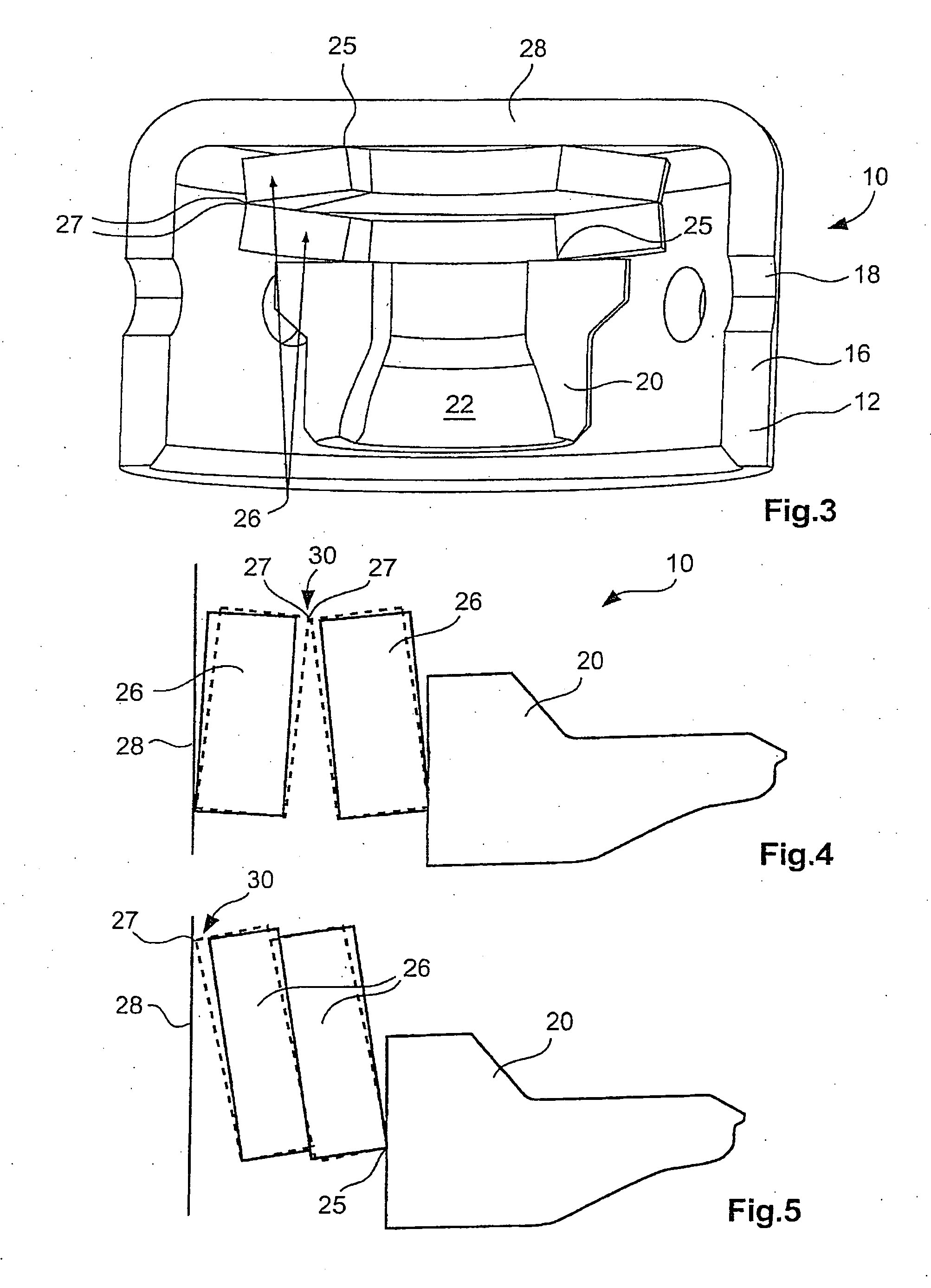
[0047]FIGS. 10 and 11 show a fifth and the gas generator 10 of the invention, in which the component immovable relative to the outer housing, in which a plurality of outflow openings 22 are formed here, is formed by a pot-shaped cap 34 arranged inside the chamber 14. The cap 34 surrounds an opening 36 of the chamber, which in the non-activated condition of the gas generator 10 is closed by a membrane 24. The outflow openings 22 are arranged on the periphery of the cap 34 and in the normal position are closed by a plurality of resilient elements 26, which are disc springs that are arranged one above the other and complement each other to form a bellows-like structure. The outer edges 27 (FIG. 10) and the inner edges 25 (FIG. 11) of the resilient elements 26 rest against the periphery of the cap 34. In the aspect as shown in FIG. 10, the resilient elements 26 are arranged behind the outflow openings 22, but before the membrane 24 with respect to the flow path of the compressed gas. In...


PUM


Abstract

A gas generator, in particular for a vehicle occupant restraint system, has a rigid outer housing (12), a chamber (14) formed in the outer housing (12), in which a compressed gas is present at least upon activation of the gas generator (10), a component immovable (20; 34; 62), at least one outflow opening (22) formed in the component immovable (20; 34; 62) relative to the outer housing (12), and at least one substantially flat, resilient element (26), which is clamped inside the outer housing (12) and rests against the immovable component (20; 34; 62) at least in its normal position. In its normal position, the resilient element (26) closes a flow path between the chamber (14) and external surroundings of the gas generator (10) and is deformed elastically under the influence of compressed gas, whereby it clears a flow cross-section (30) whose size is increasing with increasing pressure.

Description

TECHNICAL FIELD[0001]This invention relates to a gas generator, in particular for a vehicle occupant restraint system.BACKGROUND OF THE INVENTION[0002]Such gas generator serves to generate compressed gas, by means of which for instance a gas bag of the vehicle occupant restraint system is filled in a case of restraint. For this purpose, the gas generator can include a chamber with stored cold gas, which is released upon activation of the gas generator. Alternatively or in addition (the latter in the case of so-called hybrid gas generators), the gas generator includes a combustion chamber with a pyrotechnical propellant, upon deflagration of which compressed gas is generated. The gas released upon activation of the gas generator emerges from the gas generator through one (or more) outflow opening(s), the outflow opening usually being closed by a sealing material or membrane prior to activation. Once the outflow opening is opened, it has a constant cross-section. However, the outflow ...

Claims


Application Information

Patent Timeline
IPC IPC(8): B60R21/26
CPCB60R21/26B60R2021/26094
Inventor GABLER, MICHAELENGLBRECHT, KARLKRAUS, DANIELLABITZKE, STEFANNOBACH, THOMASPRITZ, HELMUTSEIDL, JOHANN
Owner TRW AIRBAG SYST
Why Eureka
Try Eureka