Adjustment device for a disk brake

A disc brake and adjustment device technology, applied in the components of the brake, the type of the brake, the brake on the axial direction, etc., can solve the problem of large error, etc., and achieve the effect of reducing the increase of the error and saving the structure space

Inactive Publication Date: 2018-03-27
KNORR-BREMSE SYST FUER NUTZFAHRZEUGE GMBH
View PDF11 Cites 0 Cited by
  • Summary
  • Abstract
  • Description
  • Claims
  • Application Information

AI Technical Summary

Problems solved by technology

The disadvantage of the solution of EP 1 546 571B1 is that this precise air gap adjustment still involves relatively large errors

Method used


Image

  • Adjustment device for a disk brake

Examples


Embodiment Construction

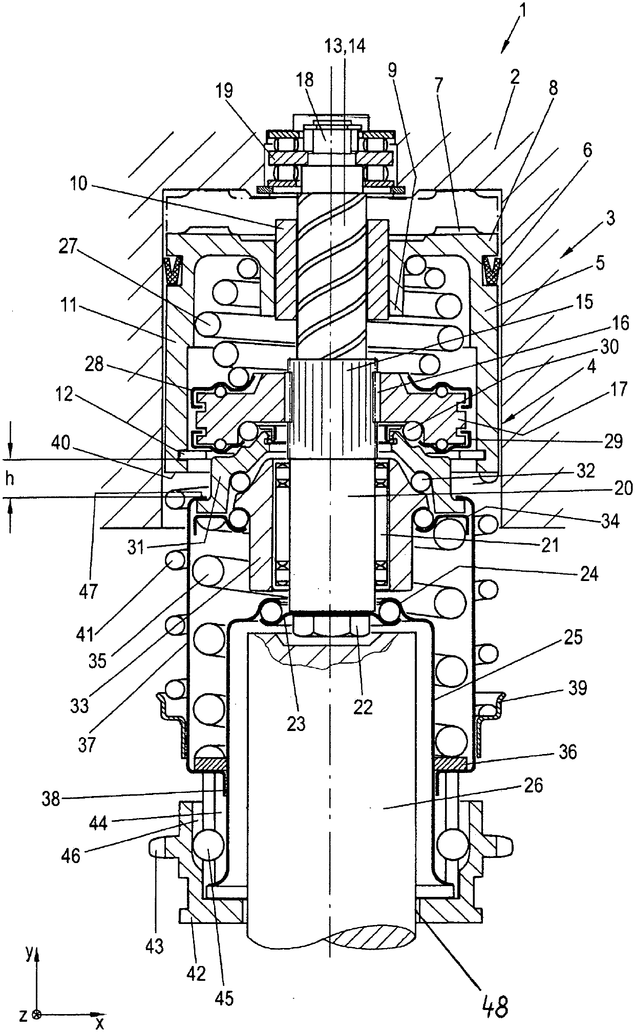
[0021] figure 1 A front sectional view of the adjustment device is shown. The adjusting device 1 is installed or can be installed in a brake caliper 2 of a (otherwise not shown here) disc brake which (in addition to the adjusting device or a plurality of adjusting devices therein) can for example It is designed in the manner of EP 1 546 571 B1, that is to say it has a pneumatically actuatable pressing device (not shown here) for pressing the brake during braking.

[0022] The adjusting device 1 has a pneumatically actuatable (ie can be acted upon with compressed air) actuator 3 . The adjusting device 1 can thus advantageously be activated independently of a brake actuation. The pneumatically actuatable actuator 3 has a cylinder 4 . Inserted in the cylinder 4 is a piston 5 which is axially displaceable in the cylinder 4 and can be acted upon by compressed air. The piston 5 has a seal 6 which is inserted into a groove in the piston 5 . Sealing member 6 will cylinder body 4 ...


PUM


Abstract

The invention relates to an adjustment device (1) for a pneumatically actuatable disk brake for a vehicle, which adjustment device is designed to compensate wear between a brake lining or a pluralityof brake linings and / or a brake disk, wherein the adjustment device has at least the following: a pneumatic actuator device (3), which has a cylinder (4), into which an axially movable piston (5) is inserted, to which compressed air can be applied and which can be moved in a first direction by application of compressed air; a non-self-locking threaded drive (10, 13, 14), which has a threaded nut (10) and a threaded shaft (13); wherein the piston (5) is coupled to the threaded nut (13) in a rotationally fixed manner and wherein the threaded shaft (13) rotatably extends through the threaded nut(10). Said adjustment device is distinguished in that at least one restoring spring (27, 41) is provided, by means of which the piston (5) can be moved in the cylinder (4) in a second direction opposite the first direction, and the adjustment device (1) is designed in such a way that the adjustment device performs an advancing stroke as a result of application of compressed air to the piston (5) and performs a restoring stroke in a spring-actuated manner as a result of the spring force of the at least one restoring spring (27, 41).

Description

technical field [0001] The invention relates to an adjusting device for a pneumatically actuated disc brake according to the preamble of claim 1 . Background technique [0002] Adjusting devices, mechanically actuated via a pressing device, such as a rotary lever, are well known in the prior art for adjusting the brake linings of a pneumatically actuatable disc brake of a vehicle to compensate for the braking force. Wear on linings and discs. Such mechanically actuated adjustment devices have proven themselves to be feasible, but often have the disadvantage of requiring a relatively large installation space. Furthermore, in such a mechanically actuated adjusting device, the activation of the adjusting function is dependent on the actuation of the brake, so that an adjusting movement can only be achieved during actuation of the service brake. [0003] EP 1 546 571 B1 of the same type describes a pneumatic actuation adjustment which can be activated independently of the brak...

Claims


Application Information

Patent Timeline
Patent Type & Authority Applications(China)
IPC IPC(8): F16D65/56
CPCF16D65/567F16D55/22F16D2125/06
Inventor J·鲍姆加特纳
Owner KNORR-BREMSE SYST FUER NUTZFAHRZEUGE GMBH
Why Eureka
Try Eureka