Foldable wheelchair with extensible link assembly and method

a wheelchair and extensible link technology, applied in the field of foldable wheelchairs, can solve the problems of poor user posture and positioning, loose backrest upholstery, poor stability of users,

Active Publication Date: 2008-06-10
KI MOBILITY
View PDF25 Cites 39 Cited by
  • Summary
  • Abstract
  • Description
  • Claims
  • Application Information

AI Technical Summary

Benefits of technology

[0016]The foldable wheelchair frame assembly of the present invention comprises, briefly, a pair of side frames; a cross-bracing frame assembly coupling the side frames together for movement of the side frames transversely between a spaced apart deployed position and a proximate folded position; and a link assembly mounted in the cross-bracing assembly between at least one of the side frames and a remainder of the cross-bracing frame assembly with the link assembly being formed for variation of the overall length of the link assembly in a direction extending transversely between the side frames to prevent forcing of the side frames into unparallel movement during movement of the side frames between the deployed position and the folded position. The link assembly preferably is pivotally coupled at one end to the side frame and pivotally coupled at the other end to the remainder of the cross-bracing frame assembly, and the link assembly advantageously is extensible and retractable, including a slidable link member reciprocally mounted in a sleeve for relative extension and retraction of one of the sleeve and the slidable link during movement of the side frames between the deployed and folded positions. The extensible link assembly also preferably is bi-stable, for example, by moving along an arcuate path over a center line with one of the sleeve and the slidable link member being biased by spring biasing means to an extended condition on either side of the center line to provide the bi-stable over-center linkage.
[0017]A method of providing a foldable wheelchair frame is also provided which comprises, briefly, the steps of coupling a pair of side frames together by a cross-bracing frame assembly formed for lateral movement of the side frames between a deployed position and a folded position; and mounting at least one link assembly in the cross-bracing frame assembly between at least one of the side frames and a remainder of the cross-bracing frame assembly for lateral movement of the link assembly to enable the side frames to move between the deployed and the folded positions without being forced to an unparallel movement causing the upholstery to bind the frame assembly.

Problems solved by technology

Several problems have bee encountered in connection with X-tube folding wheelchair designs.
Loose backrest upholstery, however, has the substantial disadvantage of being very poor for user posture and positioning, and therefore, employing loose backrest upholstery is not a good “solution” to accommodating the arcuate movement of the side frames induced by X-tube cross bracketing assembly during folding and unfolding.
An additional problem in conventional X-tube folding wheelchairs is that seat rails or tubes are provided on the upper ends of the X-tubes of the cross-bracing assembly.
This over and under design, however, results in a higher positioning of the seat upholstery and some additional weight in the overall wheelchair frame due to lengthier cross-bracing X-tubes which are required.
Moreover, positioning the seat rails carried by the X-tubes over the uppermost side frame tubes interferes with the ability to have the backrest upholstery supporting frame members fold or pivot downwardly over the seat side frames to further reduce the bulk of the wheelchair.
This approach, however, is relatively complex and requires numerous parts which must be telescoped and slid vertically together over substantial distances.
The complexity of this solution and its attendant weight are substantial.

Method used


Image

  • Foldable wheelchair with extensible link assembly and method
  • Foldable wheelchair with extensible link assembly and method
  • Foldable wheelchair with extensible link assembly and method

Examples


Embodiment Construction

[0035]Reference will now be made in detail to the preferred embodiments of the present invention, examples of which are illustrated in the accompanying drawings. While the invention will be described in connection with the preferred embodiments, it will be understood that they are not intended to limit the invention to those embodiments. On the contrary, the invention is intended to cover alternatives, modifications and equivalents, which may be included within the spirit and scope of the invention, as defined by the appended claims.

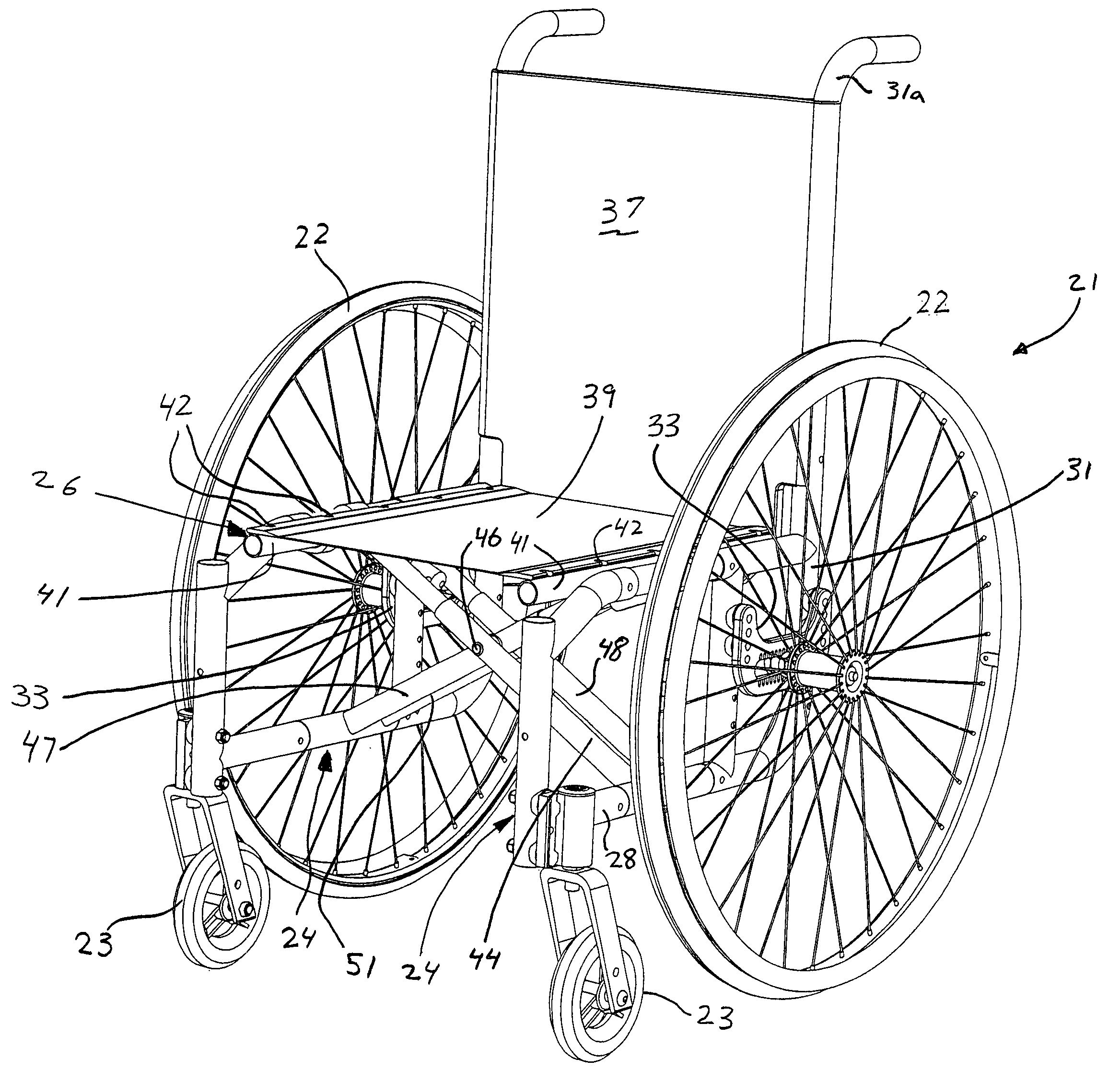
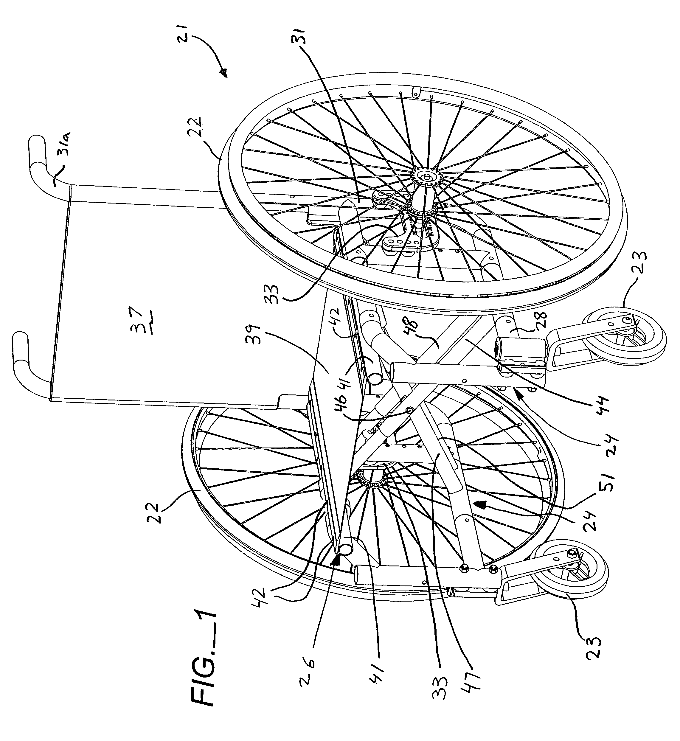
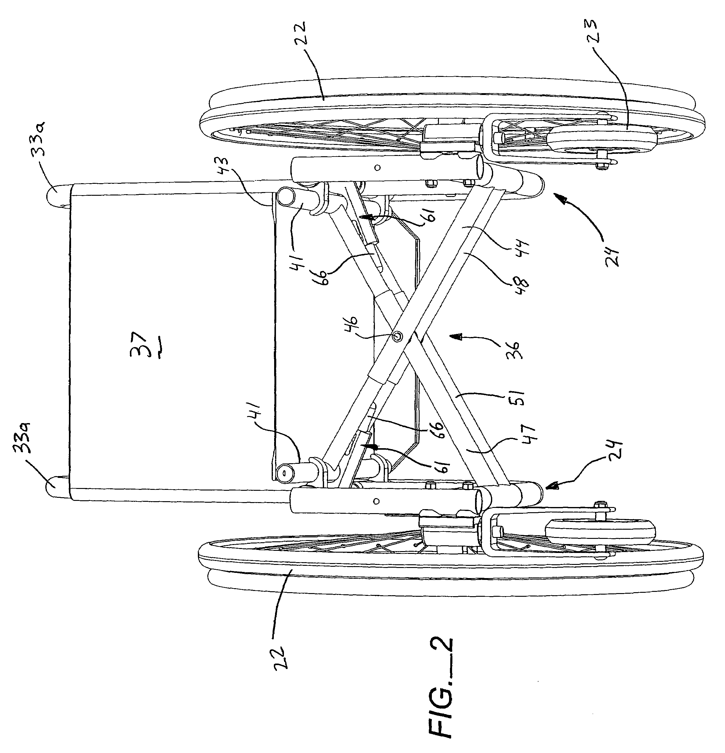
[0036]In FIGS. 1-6, an embodiment of the present foldable wheelchair, generally designated 21, is shown in which the X-tube cross-bracing assembly includes two pairs of X-tubes between which an extensible link assembly of the present invention is mounted. In FIGS. 8 and 9, the extensible link assemblies have been mounted to short downwardly depending arms, rather than directly to the side frames, and in FIGS. 9 and 10 the link assembly is comprised of me...


PUM


Abstract

A foldable wheelchair (21) and foldable wheelchair frame assembly (26, 126) including a pair of side frames (24, 124, 224, 324), a cross-bracing frame assembly (36, 136) coupling the side frames (24, 124, 224, 324) together for movement transversely between a spaced apart deployed position and a proximate folded position. A variable length link assembly (61, 161, 261, 361) is mounted into and forms a part of the cross-bracing frame assembly (36, 136) in a position between at least one of the side frames (24, 124, 224, 324) and a remainder of the cross-bracing frame assembly. The extensible link assembly (61, 161, 261, 361) being formed for variation of the overall length in a direction extending transversely between the side frames (24, 124, 224, 324) during movement of the side frames (24, 124, 224, 324) between the deployed and the folded positions so as not to force the side frames (24, 124, 224, 324) into unparallel motion which causes the upholstery to bind the folding mechanism. The extensible link assembly (61, 161, 261, 361) is preferably and over-center linkage that is resiliently biased to the extended position. A method of providing a foldable wheelchair frame assembly (26, 126) is also disclosed.

Description

TECHNICAL FIELD[0001]The present invention relates, in general, to foldable wheelchairs, and more particularly, relates to wheelchairs which have X-shaped cross-bracing frame assemblies that fold or scissor to allow the side frames of the wheelchairs to be moved between a spaced apart deployed position for use and a folded position for storage or transport.BACKGROUND ART[0002]Wheelchairs have become more portable and lightweight over the years to meet the needs of the active lives of their users. Portability has been improved by providing for so-called “folding” frame wheelchairs, which increase wheelchair portability over rigid or non-folding frame wheelchairs. One of the most popular approaches to providing a foldable or collapsible wheelchair is to couple the side frames of the chair together by a cross-bracing assembly in which the cross-bracing members, which are almost always tubes, are pivotally coupled together proximate their midpoints in an “X” shape. The X-tubes of the cr...

Claims


Application Information

Patent Timeline
Patent Type & Authority Patents(United States)
IPC IPC(8): B62B7/00B62B3/02
CPCA61G5/08A61G2005/1054A61G2005/0825A61G5/1054A61G5/0825
Inventor MUNSEY, DOUGLAS H.SLAGERMAN, MURRAY G.
Owner KI MOBILITY
Why Eureka
Try Eureka