Vehicle drive device

a technology of drive device and friction engagement device, which is applied in the direction of dynamo-electric gear control, machines/engines, transportation and packaging, etc., can solve the problems of eccentricity of the rotary members on both sides of the friction engagement device, and the load acting on the bearings that support the rotary members can become larger, so as to reduce the torque transfer to the output member via the third rotary element of the differential gear device, the effect of reducing the engagement pressure of the friction engagemen

Inactive Publication Date: 2012-10-25
AISIN AW CO LTD
View PDF3 Cites 20 Cited by
  • Summary
  • Abstract
  • Description
  • Claims
  • Application Information

AI Technical Summary

Benefits of technology

[0023]According to the configuration, the first rotary electric machine is subjected to the rotational speed control performed by the first rotary electric machine during the alignment operation. Thus, when the engagement pressure of the friction engagement device is reduced to reduce torque transferred to the second rotary element of the differential gear device via the friction engagement device, the absolute value of torque of the first rotary electric machine transferred to the first rotary element is also decreased in order to maintain the rotational speed of the first rotary electric machine. As a result, torque trans...

Problems solved by technology

Therefore, the rotary members on both sides of the friction engagement device may become eccentric with respect to each other, because the axis adjustment function due to rotation of the rotary members themselves may not be a...

Method used


Image

  • Vehicle drive device
  • Vehicle drive device
  • Vehicle drive device

Examples


first embodiment

1. First Embodiment

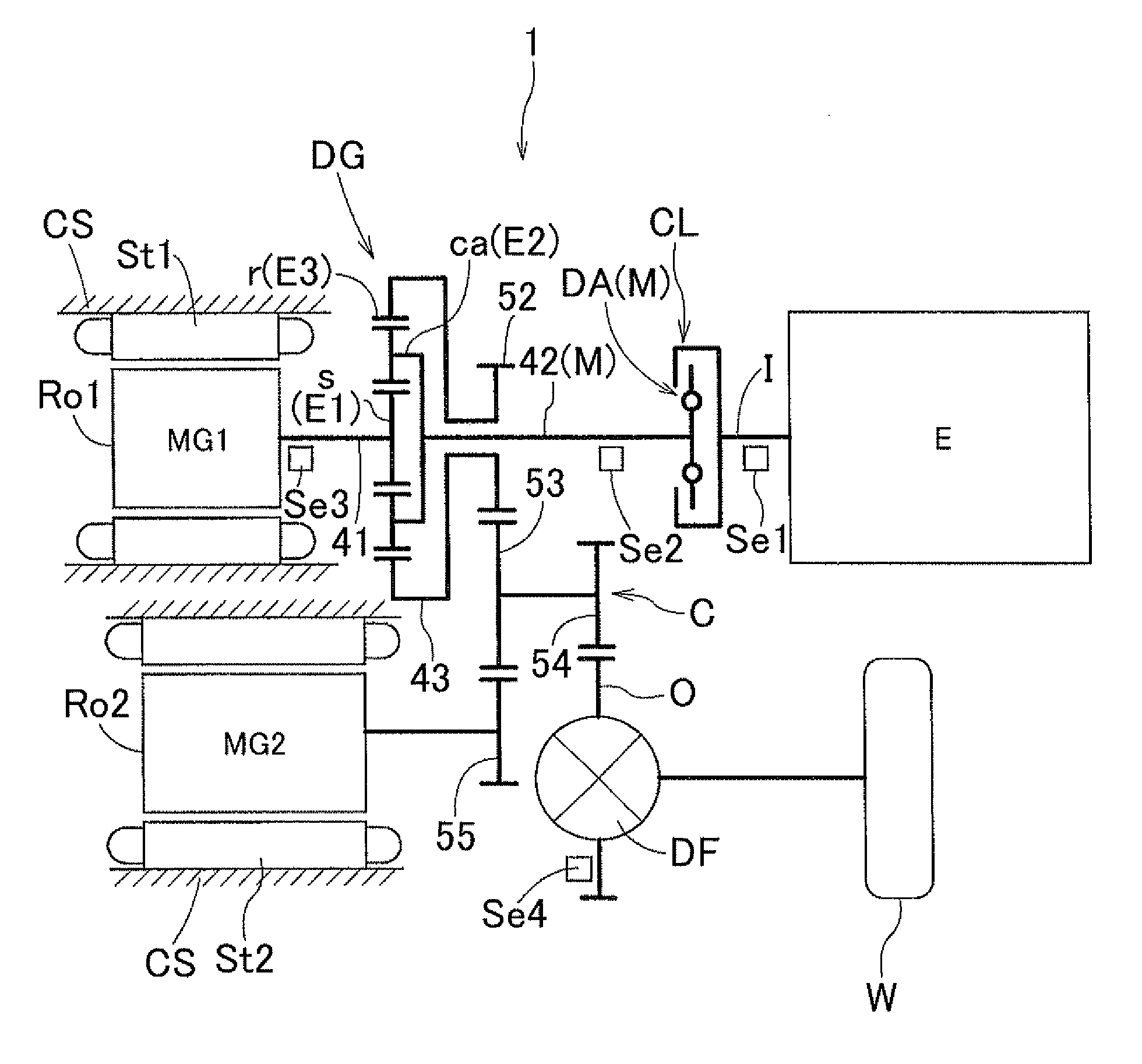
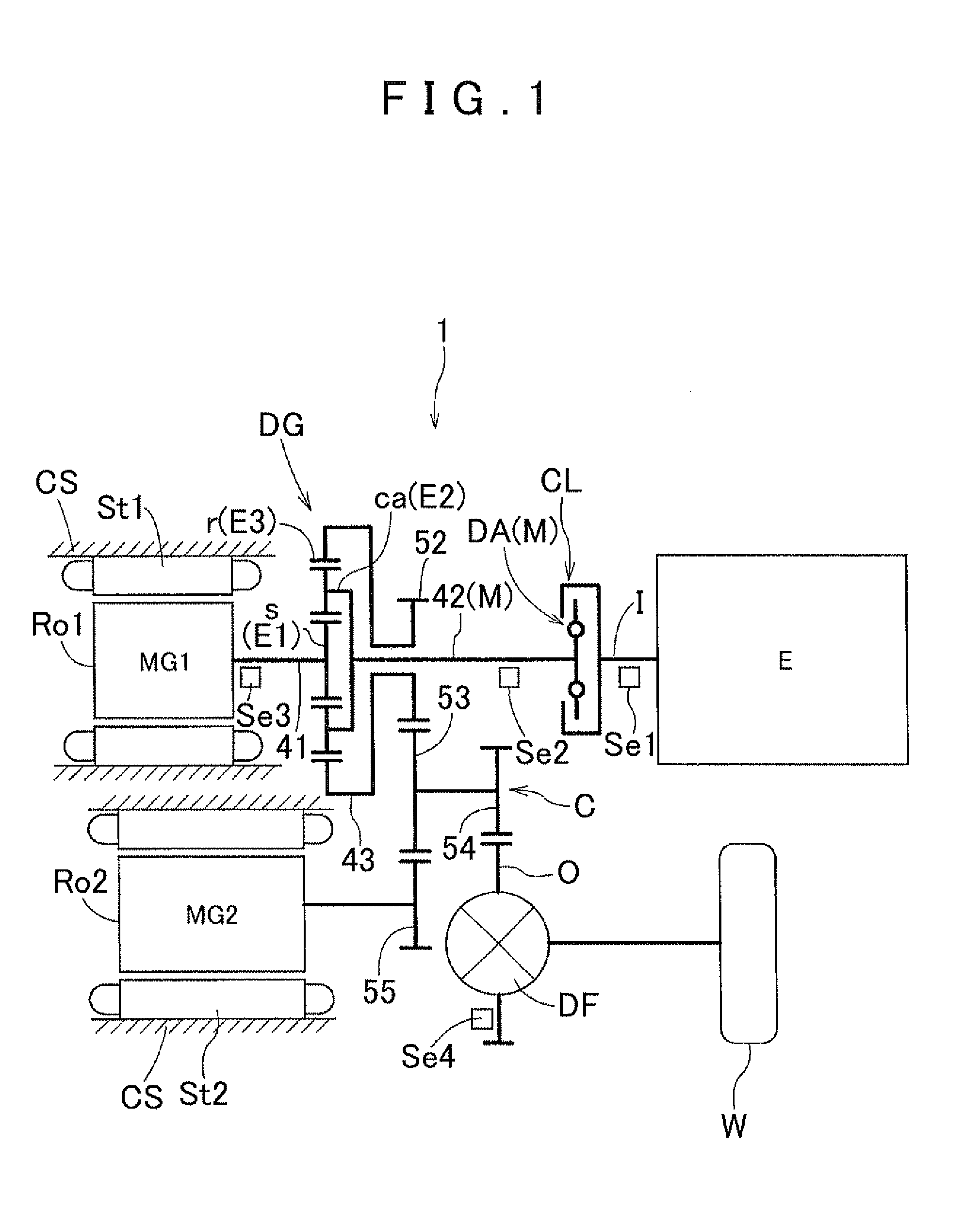
[0037]A vehicle drive device according to a first embodiment of the present invention will be described with reference to the drawings. As shown in FIG. 1, a vehicle drive device 1 according to the embodiment is a drive device (hybrid vehicle drive device) that drives a vehicle (hybrid vehicle) including an internal combustion engine E and rotary electric machines MG1 and MG2 each serving as a drive force source for wheels W. The vehicle drive device 1 according to the embodiment also includes a control device 70 (see FIG. 3). The control device 70 controls operation of the drive force sources and so forth on the basis of the system configuration shown in FIG. 3. In FIG. 3, broken lines each indicate a transfer path for electric power, and solid arrows each indicate a transfer path for various types of information.

[0038]In the embodiment, as shown in FIG. 1, a differential gear device DG provided in the vehicle drive device 1 is formed by a planetary gear mechanis...

second embodiment

2. Second Embodiment

[0122]A vehicle drive device according to a second embodiment of the present invention will be described with reference to the drawings. The vehicle drive device 1 according to the embodiment is different from the first embodiment described above mainly in the method to determine completion of the axis adjustment performed by the alignment control section 77 and the associated configuration. The differences between the configuration of the vehicle drive device 1 according to the embodiment and that according to the first embodiment described above will be mainly described below. The same elements as those in the first embodiment described above will not be specifically described.

[0123]The alignment control section 77 determines completion of the axis adjustment at least on the basis of the rotational speed difference ΔN between the input member I and the intermediate member M as in the first embodiment described above. In the embodiment, further, the alignment co...


PUM


Abstract

A vehicle drive including an input coupled to an engine, an output coupled to wheels, an intermediate member between the input and output and coupled to a rotary electric machine, a friction engagement device between the input and intermediate member, and a control device. The control device, when starting the engine with the friction engagement device disengaged, engages the friction engagement device when a rotational speed difference between the input and intermediate member is equal to or less than a predetermined value; raises a rotational speed of the input using the rotary electric machine with the friction engagement device engaged to start the engine; and, when a rotational speed of the engine is equal to or more than a predetermined value, reduces an engagement pressure of the friction engagement device and the friction engagement device is returned to the engaged state when the rotational speed difference reaches a threshold.

Description

INCORPORATION BY REFERENCE[0001]The disclosure of Japanese Patent Application No. 2011-094321 filed on Apr. 20, 2011 including the specification, drawings and abstract is incorporated herein by reference in its entirety.BACKGROUND OF THE INVENTION[0002]The present invention relates to a vehicle drive device including an input member drivably coupled to an internal combustion engine, an output member drivably coupled to wheels, an intermediate member provided on a power transfer path connecting between the input member and the output member and drivably coupled to a rotary electric machine, a friction engagement device capable of releasing drivable connection between the input member and the intermediate member, and a control device.DESCRIPTION OF THE RELATED ART[0003]An example of the vehicle drive device described above according to the related art is described in Japanese Patent Application Publication No. 2010-76678 (paragraphs 0075, 0076, etc.) mentioned below. The device accord...

Claims


Application Information

Patent Timeline
IPC IPC(8): B60W20/00B60W10/02B60W10/08B60L50/16
CPCB60K6/387B60K6/445B60W10/02B60W10/08B60W20/40B60W2710/025Y10T477/347F02D29/02Y02T10/6239Y10T477/26Y10T477/27Y10T477/32B60W2710/081Y02T10/62
Inventor TAKAMI, SHIGEKIATARASHI, TOMOOYAMAMOTO, YOSHIHISA
Owner AISIN AW CO LTD
Why Eureka
Try Eureka