Vehicle transmission device

a transmission device and vehicle technology, applied in the direction of vehicle position/course/altitude control, process and machine control, instruments, etc., can solve the problems of reducing the torque that can be transferred by the speed change mechanism, restricting the regenerative torque of the rotary electric machine, and reducing the regenerative torque. , to achieve the effect of reducing the braking speed of the vehicle, reducing the regenerative torque, and increasing the rotational speed of the input member

a transmission device and vehicle technology, applied in the direction of vehicle position/course/altitude control, process and machine control, instruments, etc., can solve the problems of reducing the torque that can be transferred by the speed change mechanism, restricting the regenerative torque of the rotary electric machine, and reducing the regenerative torque. , to achieve the effect of reducing the braking speed of the vehicle, reducing the regenerative torque, and increasing the rotational speed of the input member

US20120290163A1Active Publication Date: 2012-11-15AISIN AW CO LTD

Image

  • Vehicle transmission device
  • Vehicle transmission device
  • Vehicle transmission device

Examples


Embodiment Construction

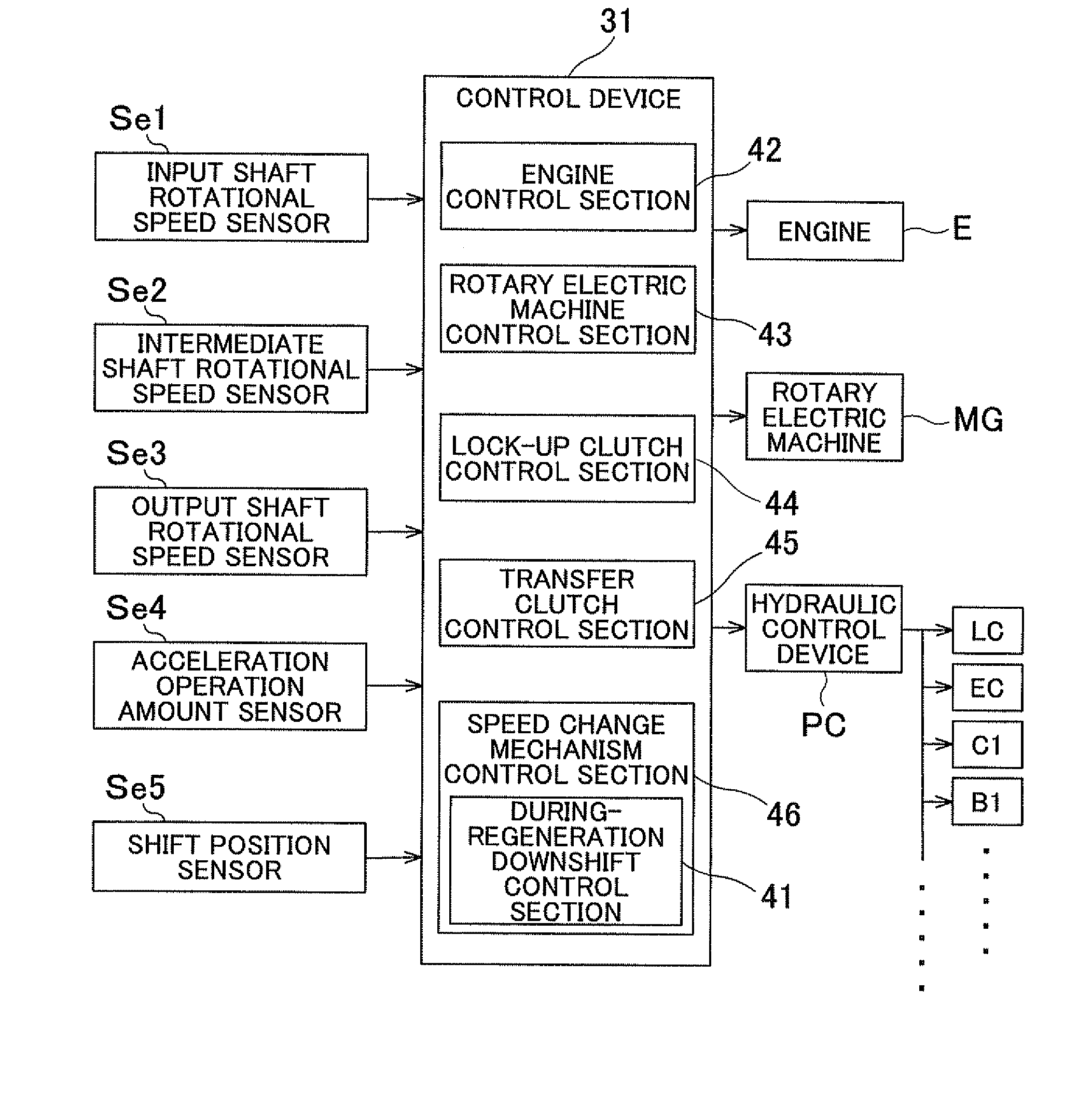
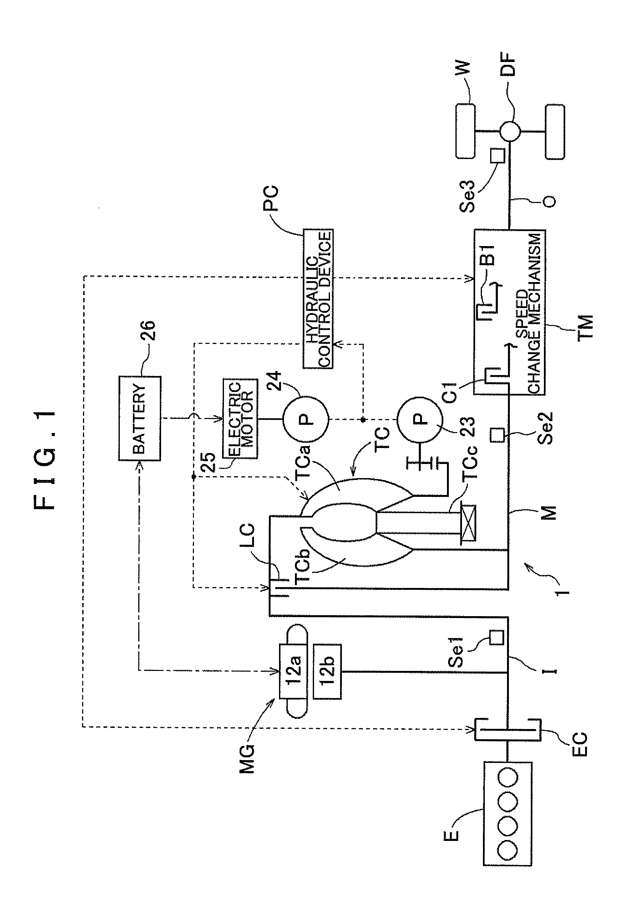
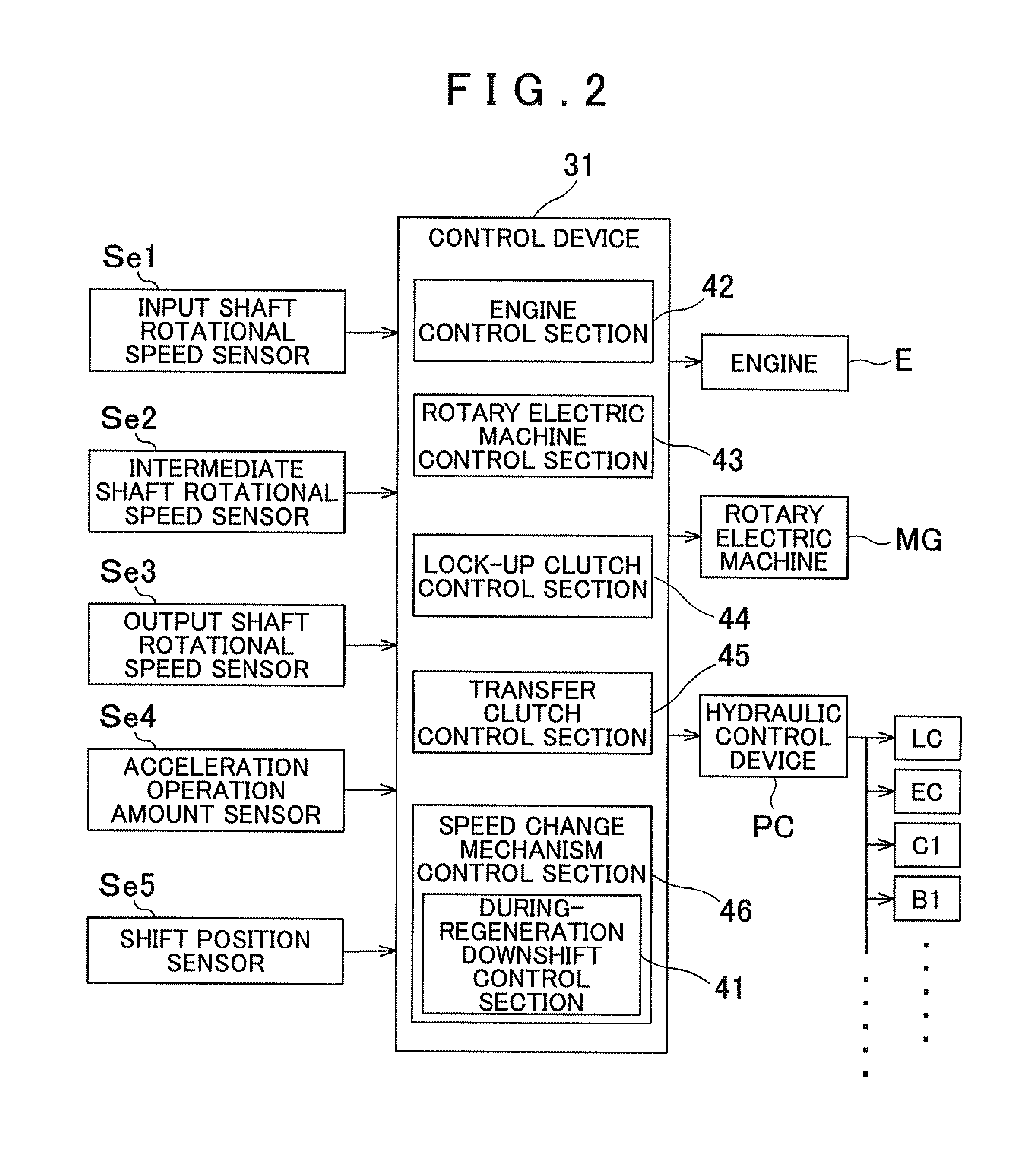
[0038]A vehicle transmission device 1 according to an embodiment of the present invention will be described with reference to the drawings. FIG. 1 is a schematic diagram showing the schematic configuration of the vehicle transmission device 1 according to the embodiment. As shown in the drawing, a vehicle incorporating the vehicle transmission device 1 is a hybrid vehicle including both an engine E, which is an internal combustion engine, and a rotary electric machine MG each serving as a drive force source. In the drawing, the solid lines each indicate a drive force transfer path, the broken lines each indicate a working oil supply path, and the dash-dotted line indicates an electric power supply path. As shown in the drawing, the vehicle transmission device 1 according to the embodiment is generally configured to include the engine E and the rotary electric machine MG each serving as a drive force source, and to transfer drive forces of the drive force sources to wheels W via a to...


PUM


Abstract

A vehicle transmission device includes an input member coupled to a combustion engine and a rotary electric machine; an output member coupled to wheels; a speed change mechanism with a plurality of friction engagement elements and that provides a plurality of shift speeds; and a control device that controls the speed change mechanism. When a during-regeneration downshift is performed while the rotary electric machine is outputting regenerative torque, the control device sets a target increase capacity, which is a target value of a transfer torque capacity of an engagement-side element to be engaged after an increase, increases the transfer torque capacity of the engagement-side element to the target increase capacity over a predetermined torque capacity increase period, and decreases a transfer torque capacity of a disengagement-side element, which is to be disengaged, over a predetermined torque capacity decrease period that at least partially overlaps the torque capacity increase period.

Description

INCORPORATION BY REFERENCE[0001]The disclosure of Japanese Patent Application No. 2010-076713 filed on Mar. 30, 2010 including the specification, drawings and abstract is incorporated herein by reference in its entirety.BACKGROUND OF THE INVENTION[0002]The present invention relates to a vehicle transmission device including an input member drivably coupled to an internal combustion engine and a rotary electric machine, an output member drivably coupled to wheels, a speed change mechanism that provides a plurality of shift speeds established by controlling engagement and disengagement of a plurality of friction engagement elements, and a control device that controls the speed change mechanism.DESCRIPTION OF THE RELATED ART[0003]A device disclosed in Japanese Patent Application Publication No. JP-A-2008-94332 below, for example, is known as a transmission device for a hybrid vehicle including an internal combustion engine and a rotary electric machine each serving as a drive force sou...

Claims


Application Information

Patent Timeline
15 Nov 2012
Publication
US20120290163A1
IPC
B60W20/00; B60W10/10; B60W10/02; B60L50/16; B60W10/115; B60W30/18
CPC
B60K6/48; Y02T10/70; B60L11/14; B60W10/02; B60W10/08; B60W10/115; B60W20/00; B60W30/18127
Inventors
INAGAKI, NOBUAKI; UENO, HIROYA