Programmable bit error rate monitor for serial interface

Inactive Publication Date: 2008-06-10
ALTERA CORP
View PDF14 Cites 16 Cited by
  • Summary
  • Abstract
  • Description
  • Claims
  • Application Information

AI Technical Summary

Problems solved by technology

It would be expected that a user would program the monitoring period counter and the error threshold of the error flag generator so that an error flag is generated when an error rate that the user's application cannot tolerate is reached.

Method used


Image

  • Programmable bit error rate monitor for serial interface
  • Programmable bit error rate monitor for serial interface
  • Programmable bit error rate monitor for serial interface

Examples


Embodiment Construction

[0017]The invention will now be described with reference to FIGS. 1-5.

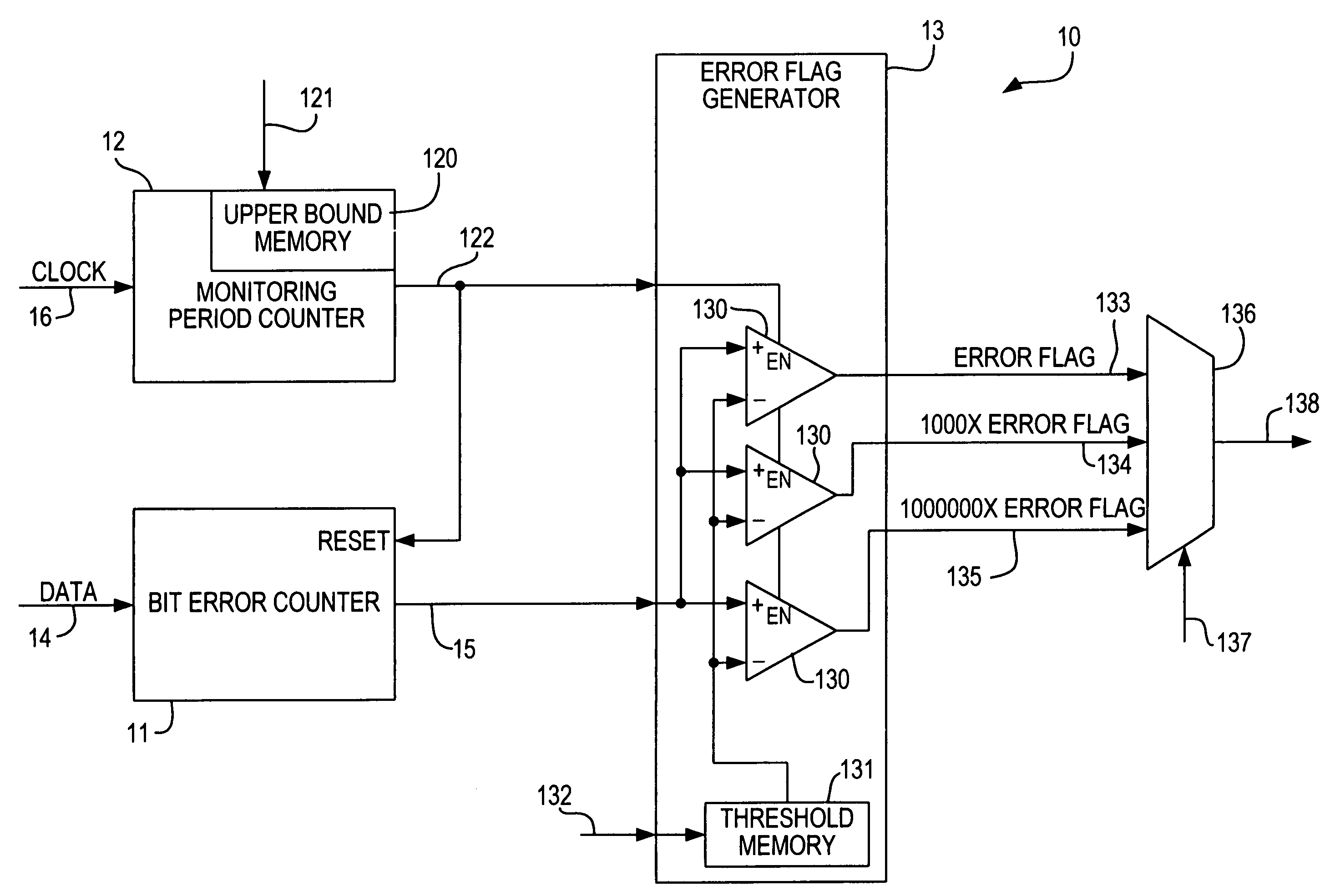
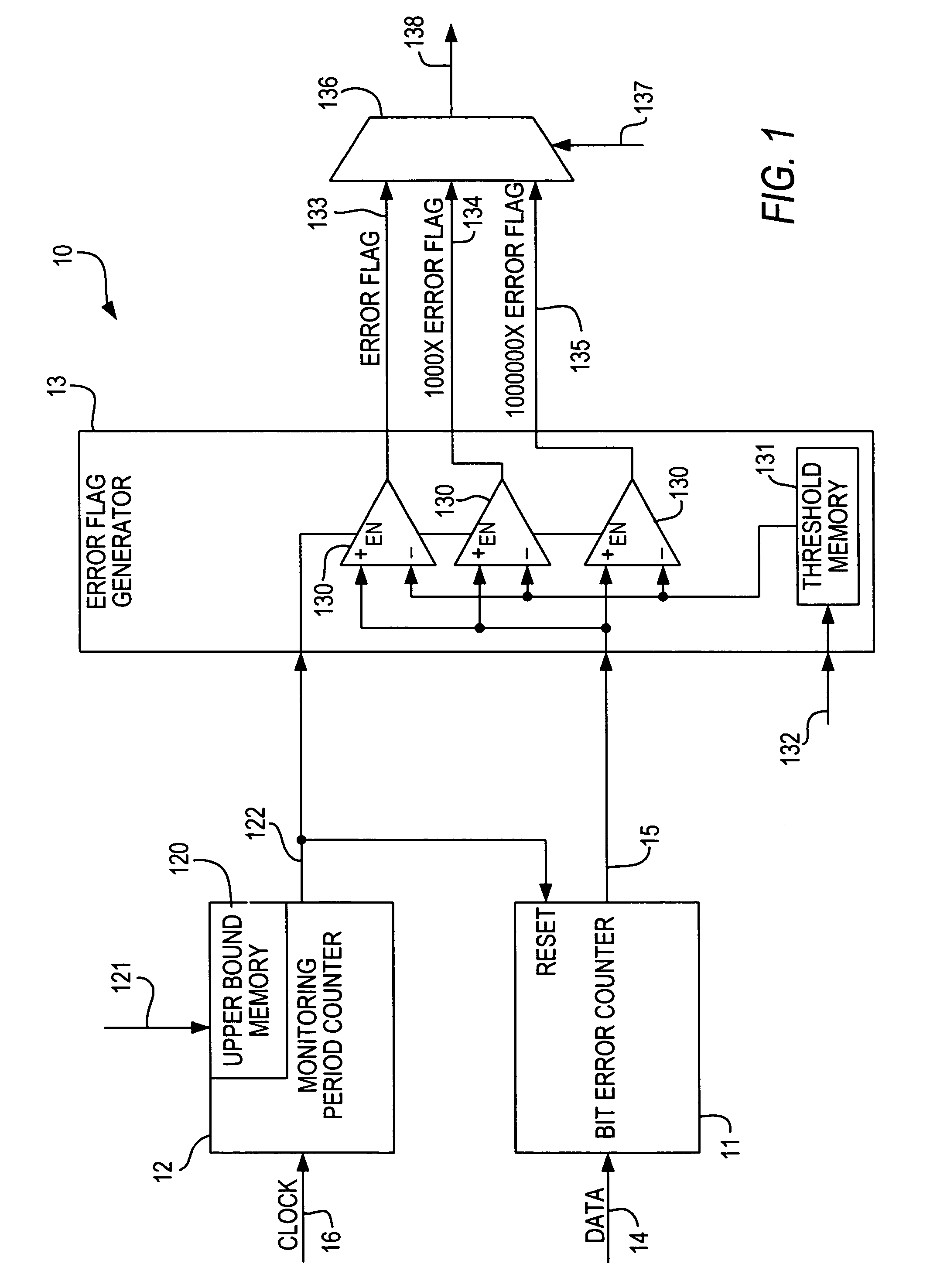
[0018]As shown in FIG. 1, a preferred embodiment of a programmable bit error rate monitor 10 in accordance with the present invention preferably includes at least a bit error counter 11, a programmable monitoring period counter 12, and an error flag generator 13. Bit error counter 11 preferably receives the data stream 14 to be monitored, and outputs at 15 a signal representative of the number of errors encountered since the last reset of bit error counter 11.

[0019]A clock signal 16 associated with data signal 14, which may be provided separately from data signal 14 or may be recovered from data signal 14 by clock recovery circuitry (not shown) as is well known, is input to programmable monitoring period counter 12. Programmable monitoring period counter 12 preferably includes a user-programmable memory 120 into which a user, via input 121, can enter an upper bound representing the duration of the monitoring perio...


PUM


Abstract

A programmable bit error rate monitor includes an error counter, a monitoring period counter with a programmable upper bound to set the monitoring period, and an error flag generator that compares the actual error count to a programmable threshold. The error flag generator may generate flags at different sensitivity levels, and the user may programmably select one of those flags. The three flags can be generated by independent comparators, or they can be extrapolated from the base error flag—e.g., by comparing only certain bits of the error count to corresponding bits of the threshold.

Description

BACKGROUND OF THE INVENTION[0001]This invention relates to a bit error rate monitor for a serial communication interface. More particularly, this invention relates to a bit error rate monitor that is programmable to allow adjustment by a user to accommodate different interfaces.[0002]Monitoring the bit error rate is important in serial communications applications. For example, the telecommunications industry closely monitors bit error rates. At various thresholds of bit error rate, a communications device may be instructed to slow down its transmission rate (and to return to its full rate when the error rate decreases), to request maintenance, to shut down or enter an idle mode, and / or to activate an alternate or back-up device.[0003]Different communications devices have different error threshold requirements (i.e., different monitoring period and threshold levels). For example, the 10-Gigabit Ethernet 64b / 66b padded protocol specification calls for monitoring two bits out of every ...

Claims


Application Information

Patent Timeline
Patent Type & Authority Patents(United States)
IPC IPC(8): G06F11/00
CPCG06F11/076G06F11/0772
Inventor XUE, NINGLEE, CHONG H
Owner ALTERA CORP
Why Eureka
Try Eureka