Ophthalmoscope

a technology of ophthalmoscope and lens, which is applied in the field of ophthalmoscope, can solve the problems of diaphragm or optical filter displacement, and achieve the effect of simple design

Inactive Publication Date: 2008-06-17
HEINE OPTOTECHN
View PDF4 Cites 24 Cited by
  • Summary
  • Abstract
  • Description
  • Claims
  • Application Information

AI Technical Summary

Benefits of technology

[0006]It is the object of the invention to provide a reliable handheld ophthalmoscope with the aid of simple design means.
[0008]In the case of the ophthalmoscope according to the invention, the respective swivel lever means can be locked in respective latch stages by locking means. This prevents the setting of the diaphragm and / or the filters from being changed when the swivel lever means is inadvertently touched. An investigator can lock the diaphragm and the filters in a position he desires.
[0009]It is advantageous for the locking means to be designed in such a way that it unlocks when a predetermined torque exerted on the swivel lever means is exceeded. This prevents the swivel lever means from being damaged when an excessive force is exerted on it.
[0011]In this embodiment, the latching depressions and a tip of the latching slide have inclined sidewalls that bear against one another in the locking position of the latching slide. The inclination angle of the sidewalls in selected such that the latching slide moves out of the latching depression when a predetermined torque is applied to the rotary element, such that damage to the swivel lever means during application of an excessively large force is prevented.

Problems solved by technology

Since the swivel lever means are supported in a freely rotatable fashion, the diaphragm or the optical filters are, however, displaced when the swivel levers are lightly touched, and this quickly comes about during improper handling.

Method used


Image

  • Ophthalmoscope
  • Ophthalmoscope
  • Ophthalmoscope

Examples


Embodiment Construction

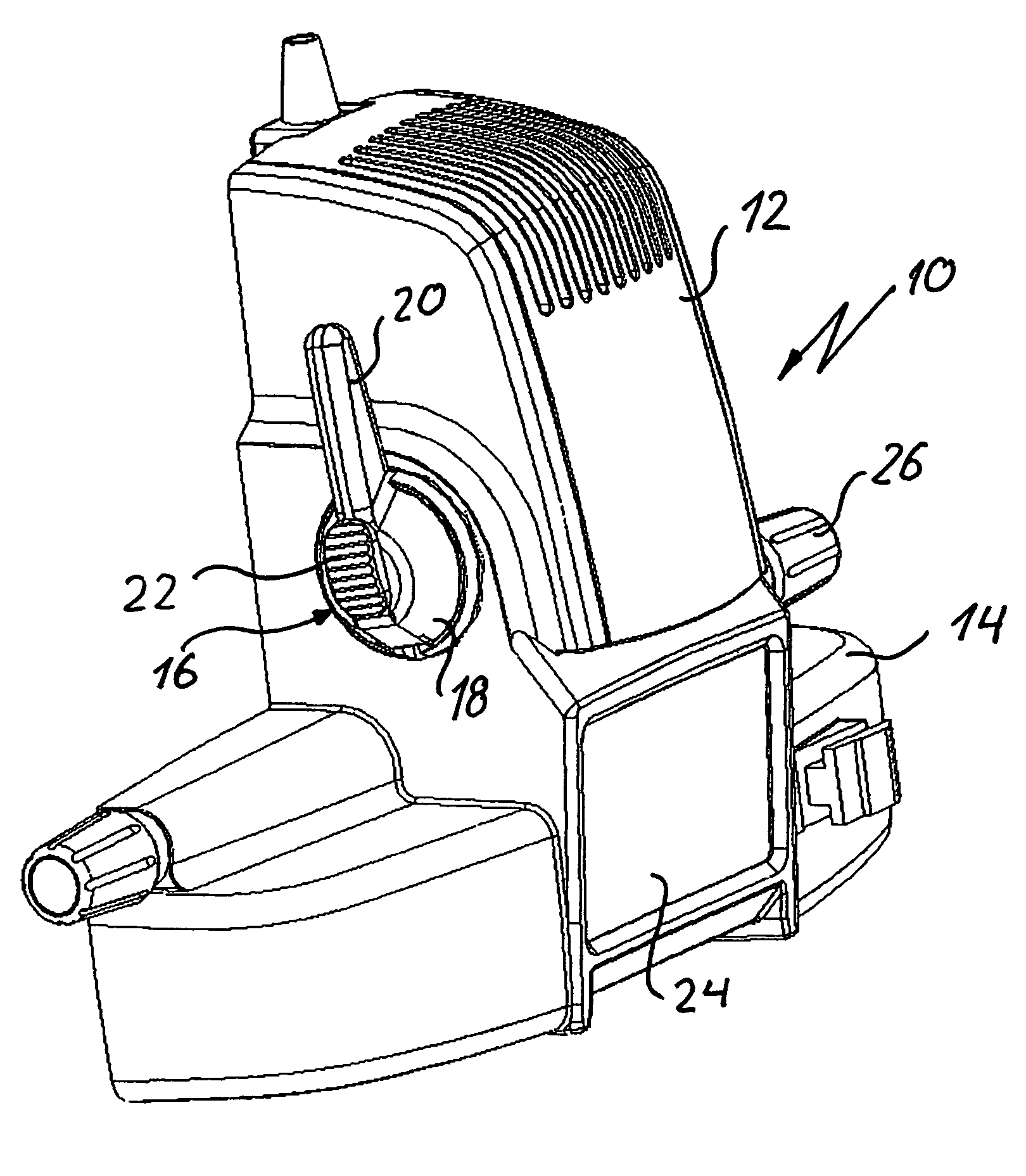
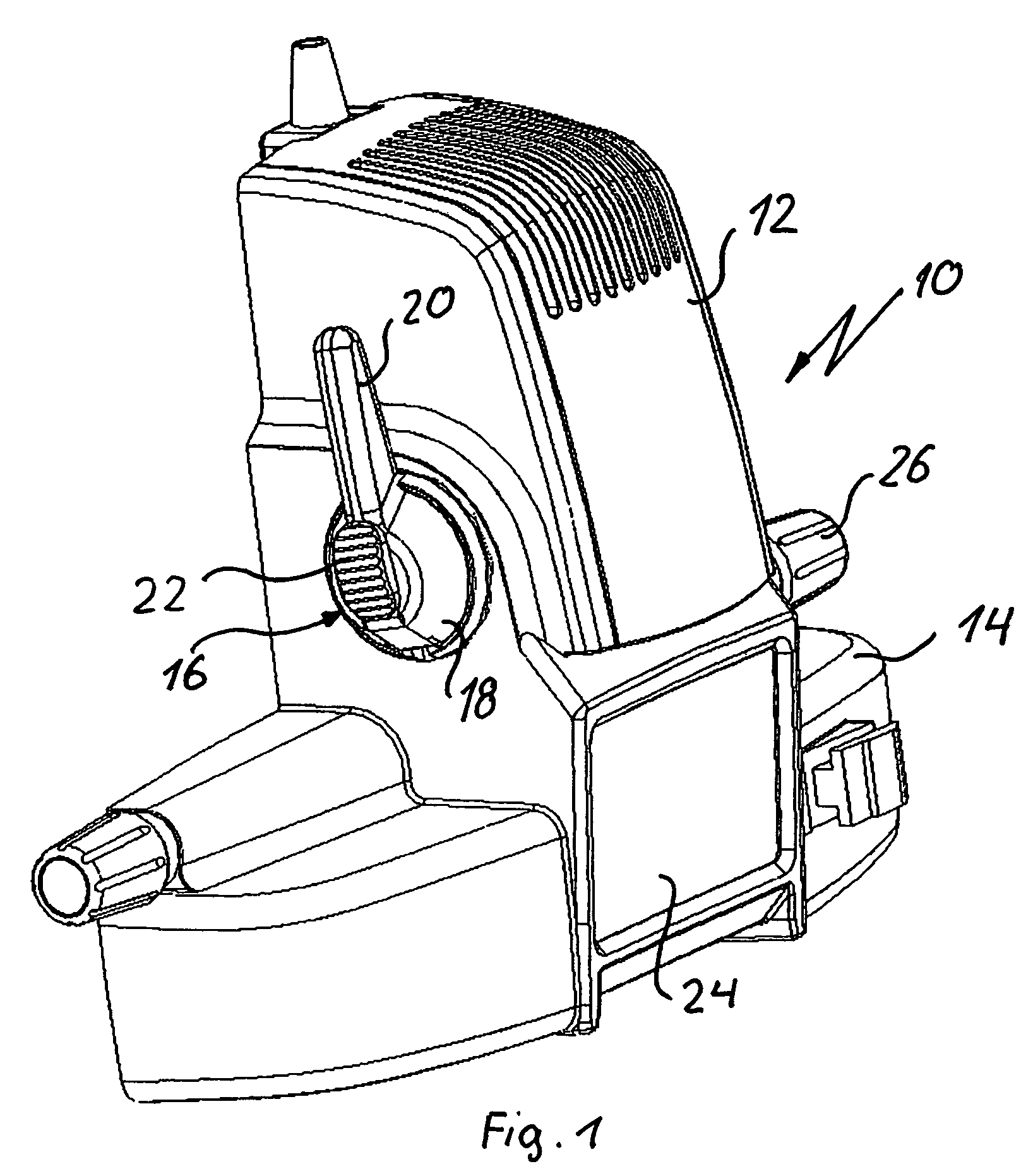
[0019]As shown in FIG. 1, the ophthalmoscope 10 according to the invention comprises a lower housing part 14 in which an observing unit is arranged behind a central glass pane 42. The observing direction of the observing unit can be set by a setting rod 26.

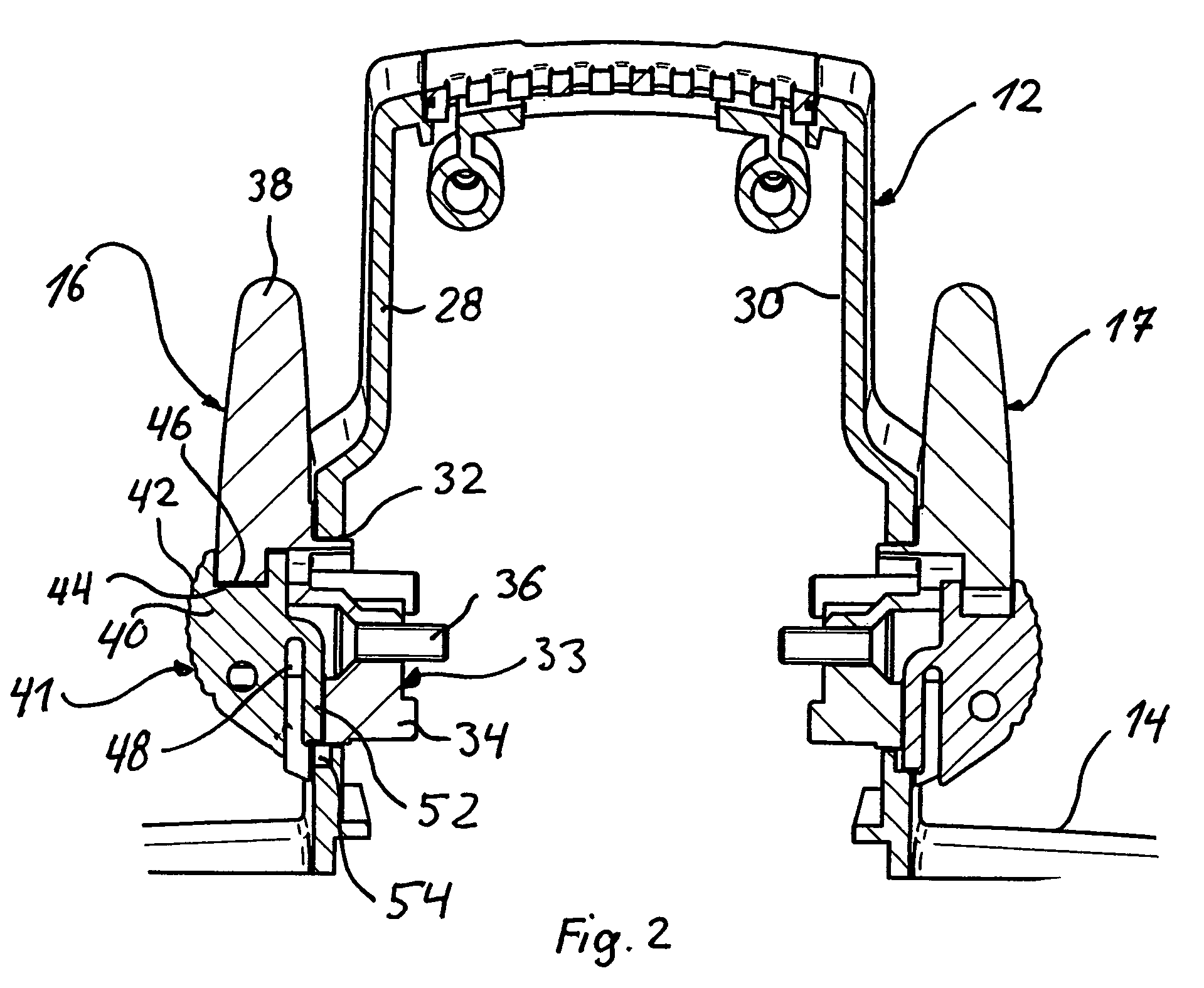
[0020]Provided above the glass pane 24 is an upper housing part 12 in which an illuminating unit with an illuminating source, for example LEDs, is accommodated. Although it is not shown in the drawings for reasons of clarity, in the case of the ophthalmoscope according to the invention, as in the case of the opthalmoscope known from U.S. Pat. No. 4,684,227, there is firstly arranged between the light source and the observing unit an adjustable diaphragm means, after which there is arranged a filter means with optical filters in the illuminating path. The diaphragm means can be set by a swivel lever means 16 via a mechanism that is not shown. The setting of the filters is enabled by a swivel lever means 17 via a mechanism (likewise...


PUM


Abstract

An ophthalmoscope includes a housing (12) in which there are arranged an observing unit and a light source between which there are / is arranged a diaphragm and / or a filter device that can be set via a swivel lever device (16, 17) mounted outside on the housing (12). The swivel lever device (16, 17) can be locked in respective latch stages by a locking device (41).

Description

BACKGROUND OF THE INVENTION[0001]1. Field of the Invention[0002]The invention relates to an ophthalmoscope having a housing in which there are arranged an observing unit and an illuminating unit between which there are / is arranged diaphragm means and / or filter means that can be set via a swivel lever means mounted outside on the housing.[0003]2. Description of the Background Art[0004]U.S. Pat. No. 4,684,227 discloses a generic binocular ophthalmoscope in whose lower housing part an observing unit is arranged by means of which an examiner can examine through a patient's pupil. An illuminating unit with a light source is accommodated in the upper housing part. An adjustable diaphragm is arranged between the light source and the observing unit. Also provided is a filter means by means of which optical filters can be moved into the illuminating path between the illuminating source and the observing unit. For the purpose of setting the diaphragm and the optical filters, there is respecti...

Claims


Application Information

Patent Timeline
Patent Type & Authority Patents(United States)
IPC IPC(8): A61B3/10A61B3/12A61B3/13G02B21/24
CPCA61B3/13
Inventor HEINE, HELMUTHEINE, OLIVERBEHRENDT, WOLFGANG
Owner HEINE OPTOTECHN
Why Eureka
Try Eureka