Vehicle alternator monitoring system and related failure monitoring method

a technology for monitoring systems and alternators, applied in the direction of electric generator control, dynamo-electric converter control, transportation and packaging, etc., can solve the problems of undesired warning provided to the vehicle driver, unfavorable monitoring of the whole control performance of the vehicle, and the fear of deterioration of the control performance of the whole vehicle, so as to minimize the processing burden of the external control devi

Active Publication Date: 2008-06-24
DENSO CORP
View PDF14 Cites 7 Cited by
  • Summary
  • Abstract
  • Description
  • Claims
  • Application Information

AI Technical Summary

Benefits of technology

[0009]The present invention has been completed with a view to addressing the issues mentioned above and has an object to a vehicle alternator failure monitoring system and related monitoring method that make it possible to obtain detailed information related to an operational failure status of a vehicle alternator while minimizing a processing burden of an external control device in monitoring a power generation status and an operational failure of the vehicle alternator.

Problems solved by technology

However, if attempt is made to allow the external control device to process power generation information having an increase in a rarely distributed failure status of the vehicle alternator, the external control device has an inordinate processing burden, resulting in the occurrence of an issue with a fear of deterioration on control performance of a whole of a vehicle.
Further, a failure state of the vehicle alternator involves a temporary voltage drop resulting form power-on operation of, for instance, a large electrical load.
Thus, with no judgment made in taking not only an operational status of the vehicle alternator but also a vehicle status into consideration in an integrated way, undesired warning is provided to the vehicle driver accompanied by promoted uneasy feeling.

Method used


Image

  • Vehicle alternator monitoring system and related failure monitoring method
  • Vehicle alternator monitoring system and related failure monitoring method
  • Vehicle alternator monitoring system and related failure monitoring method

Examples


Embodiment Construction

[0060]Now, a vehicle alternator failure monitoring system of an embodiment according to the present invention and related monitoring method are described below in detail with reference to the accompanying drawings. However, the present invention is construed not to be limited to such embodiments described below and technical concepts of the present invention may be implemented in combination with other known technologies or the other technology having functions equivalent to such known technologies.

[0061]Now, a vehicle alternator failure monitoring system of one embodiment to which the present invention is applied is described below in detail with reference to the accompanying drawings.

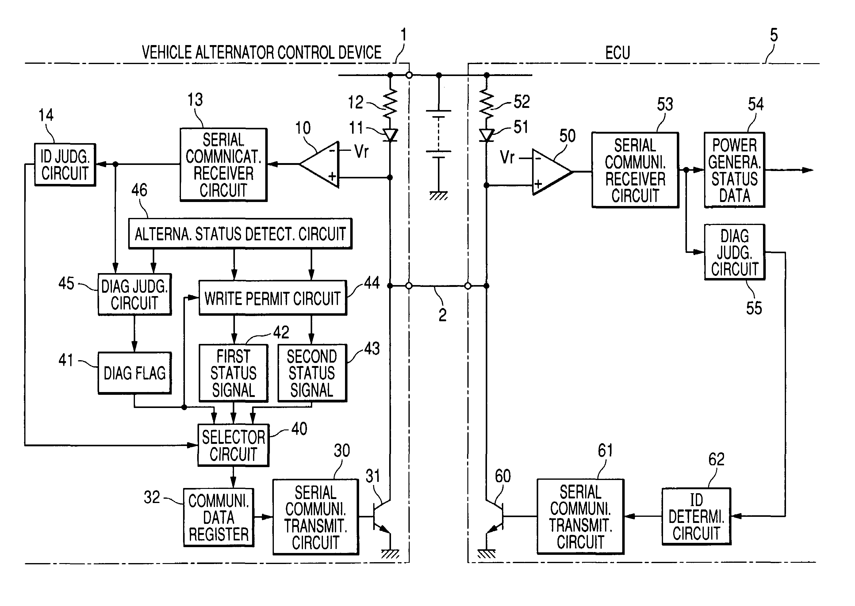
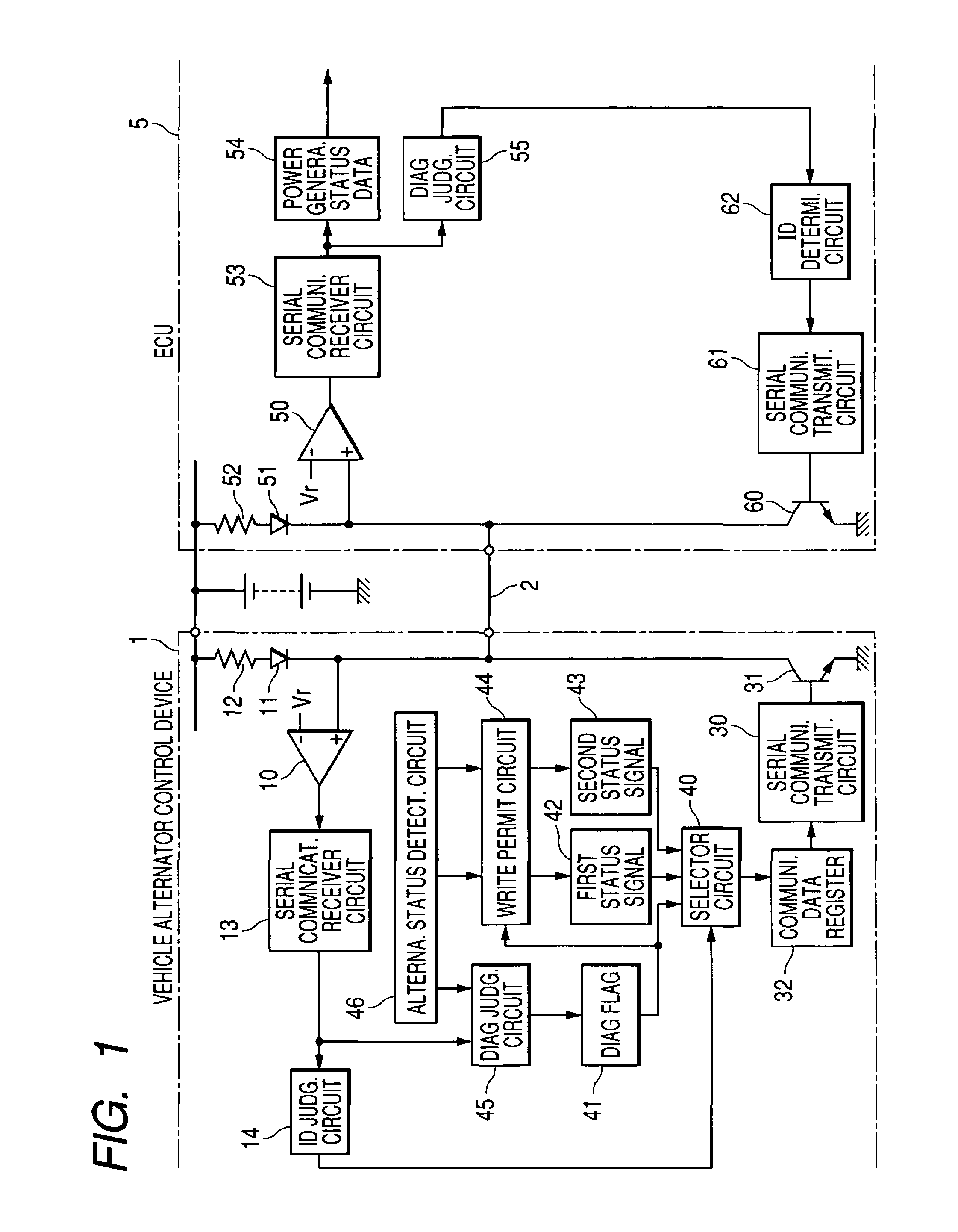
[0062]FIG. 1 is a block diagram showing a vehicle alternator control device 1 and an engine control unit (ECU) 5 with both of which the vehicle alternator failure monitoring system of the present embodiment is formed.

[0063]As shown in FIG. 1, the vehicle alternator control device 1 and the ECU 5 are c...


PUM


Abstract

A vehicle alternator failure monitoring system and related monitoring method are disclosed wherein an ECU executes operations depending on a power generation status of a vehicle alternator and a vehicle alternator control device has a serial communication transmitter circuit operative to transmit a serial communication signal, indicative of the power generation status of the vehicle alternator, to the ECU. The serial communication transmitter circuit has a first power generation status signal transmission mode in which a first power generation status signal, representing the power generation status, is transmitted together with a failure flag representing the presence of or absence of an operational failure, related to the vehicle alternator, and a second power generation status signal transmission mode in which a second power generation status signal, representing the power generation status, is transmitted together with additional data representing an operational state of the vehicle alternator.

Description

CROSS REFERENCE TO RELATED APPLICATIONS[0001]This application is based on Japanese Patent Application No. 2005-301558 filed on Oct. 17, 2005, the content of which is hereby incorporated by reference.BACKGROUND OF THE INVENTION[0002]1. Technical Field of the Invention[0003]The present invention relates to vehicle alternator failure monitoring systems and related monitoring methods and, more particularly, to a vehicle alternator failure monitoring system and related monitoring method for monitoring a power generation status and power generation failure of the vehicle alternator.[0004]2. Description of the Related Art[0005]Among control devices of the related art vehicle alternators, attempt has heretofore been made to provide a control device that, with a view to initiating rapid charging of a battery, performs power regulation control so as to maintain a power output of a vehicle operator at a fixed level (of, for instance, of 14.5V) that is fairly higher than a battery open terminal...

Claims


Application Information

Patent Timeline
Patent Type & Authority Patents(United States)
IPC IPC(8): H02J7/14
CPCH02P29/028H02P9/02H02P29/032
Inventor ASADA, TADATOSHI
Owner DENSO CORP
Why Eureka
Try Eureka