Method and apparatus for controlling image forming operation of an image forming apparatus

a technology of image forming apparatus and control method, which is applied in the direction of electrographic process apparatus, instruments, optics, etc., can solve the problems of large thermal time constant of sensors, poor responsiveness to rapid change in temperature, and delay in the first print start time, etc., and achieve the effect of small thermal time constan

Inactive Publication Date: 2008-06-24
PANASONIC CORP
View PDF12 Cites 3 Cited by
  • Summary
  • Abstract
  • Description
  • Claims
  • Application Information

AI Technical Summary

Benefits of technology

[0014]It is an object of the present invention to provide an image forming apparatus that enables the occurrence of print defects due to first print start time delay to be eliminated without using a temperature sensor that has a small thermal time constant.

Problems solved by technology

That is to say, while the use of an inexpensive temperature sensor is generally desirable with this kind of image heating apparatus in order to keep costs low, there is a drawback that an inexpensive temperature sensor normally has a large thermal time constant, and responsiveness to a rapid change in temperature is poor.
Therefore, if a temperature sensor with a large thermal time constant is used in an image forming apparatus that has a short warm-up time, there is a problem of the actual temperature of the image heating body rising before the temperature detected by the temperature sensor rises, resulting in major overshoot.
Therefore, if a temperature difference occurs between the actual temperature of the image heating body and the temperature detected by the temperature sensor as described above, there is a problem in that the first print start time is delayed in proportion to this temperature difference.
This kind of first print start time delay is pronounced when image forming is performed after the image heating body is heated from a state in which the environmental temperature of the heat-fixing apparatus is close to room temperature.
Thus, a problem with this kind of conventional image forming apparatus is that the actual temperature of the image heating body becomes higher than the predetermined image fixing temperature due to the first print start time delay, and the glossiness of the first printed sheet is abnormally high.
However, a problem associated with the use of a temperature sensor with a small thermal time constant is increased cost.

Method used


Image

  • Method and apparatus for controlling image forming operation of an image forming apparatus
  • Method and apparatus for controlling image forming operation of an image forming apparatus
  • Method and apparatus for controlling image forming operation of an image forming apparatus

Examples


embodiment 1

[0027]First, a detailed description will be given of an image forming apparatus according to Embodiment 1 of the present invention.

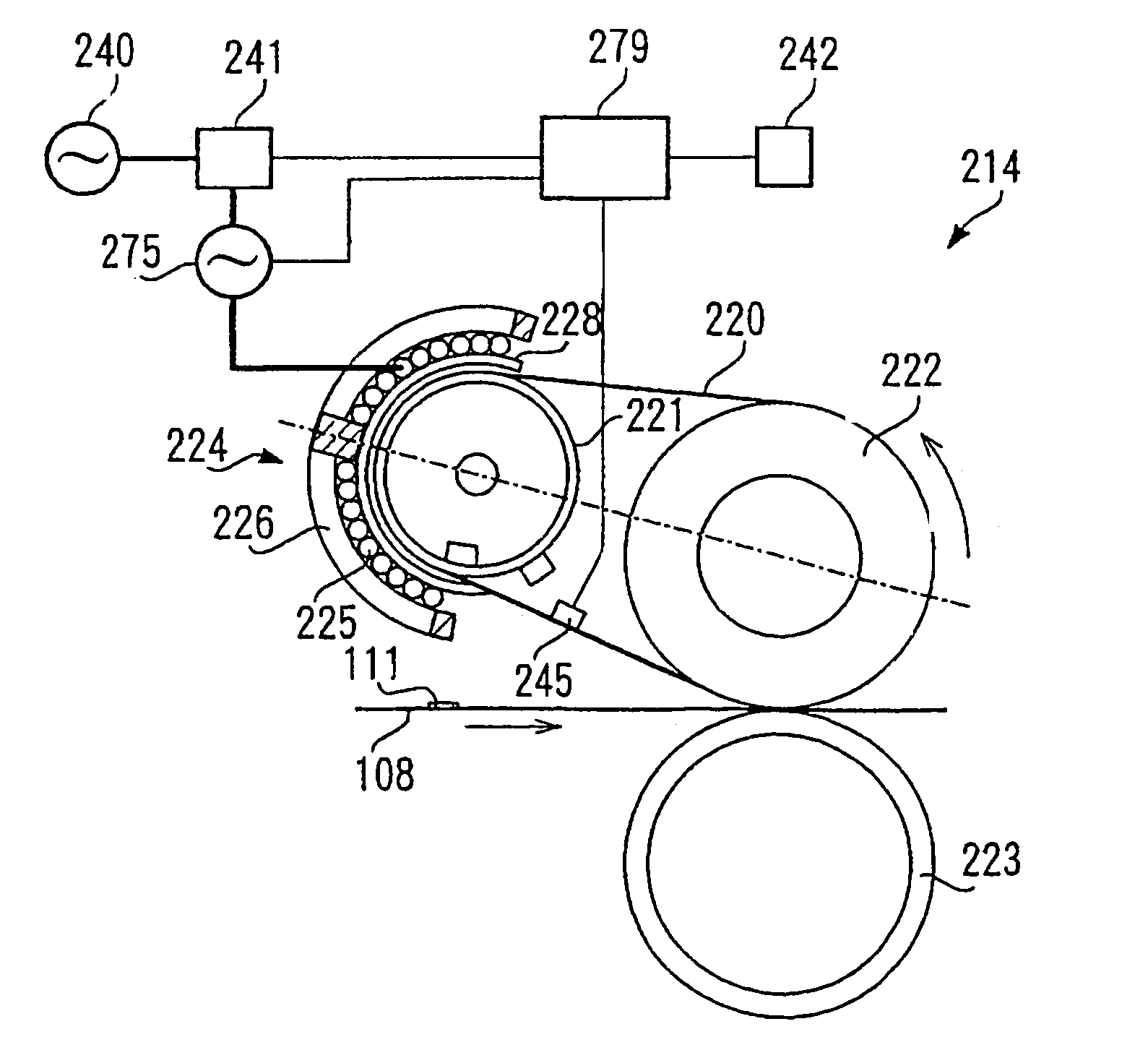
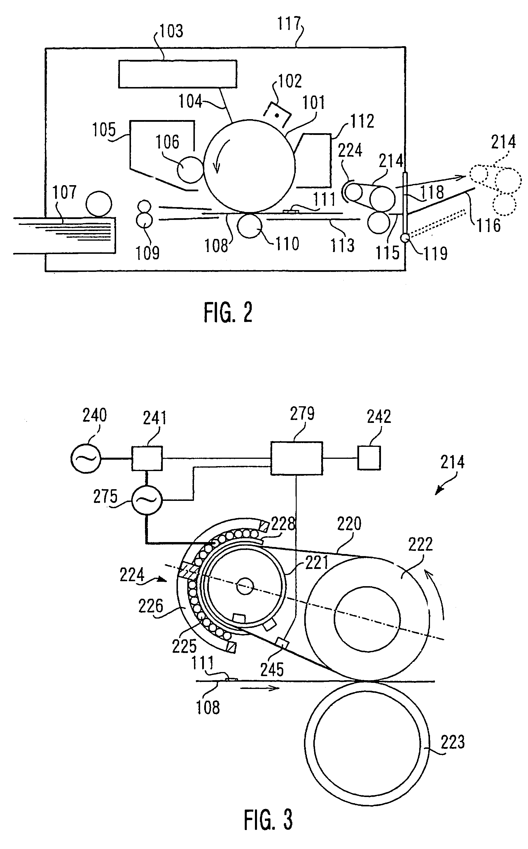
[0028]FIG. 2 is a schematic diagram showing the overall configuration of the image forming apparatus according to Embodiment 1 of the present invention. The configuration and operation of this image forming apparatus will first be described.

[0029]As shown in FIG. 2, an electrophotographic photosensitive body (hereinafter referred to as “photosensitive drum”) 101 is mounted in a freely rotatable fashion in an image forming apparatus body 117 of this image forming apparatus. In FIG. 2, photosensitive drum 101 is rotated at a predetermined circumferential speed in the direction indicated by the arrow while its surface is uniformly charged to a negative predetermined dark potential V0 by an electrifier 102.

[0030]A laser beam scanner 103 outputs a laser beam 104 modulated in accordance with a time series electrical digital pixel signal of image information in...

embodiment 2

[0088]Next, a detailed description will be given of an image forming apparatus according to Embodiment 2 of the present invention.

[0089]FIG. 9 is a schematic diagram showing the overall configuration of an image forming apparatus (color image forming apparatus) according to Embodiment 2 of the present invention.

[0090]As shown in FIG. 9, with this color image forming apparatus, opening a front door 867 attached to the front surface (the right-hand in FIG. 9) enables a transfer belt unit 868 to be inserted into and removed from the body of the apparatus. This transfer belt unit 868 is composed of an intermediate transfer belt 869, three supporting spindles 870 on which this intermediate transfer belt869 is suspended, a cleaner 871, and so forth.

[0091]On the left inside this color image forming apparatus there is installed, next to transfer belt unit 868, a tubular carriage 873 supported axially so as to be able to rotate in the direction indicated by the arrow. Inside this carriage 87...


PUM


Abstract

The present invention relates to an image forming apparatus that enables the occurrence of print defects due to a first print start time delay to be eliminated without using a temperature sensor that has a small thermal time constant. When the temperature of a fixing belt serving as an image heating body is greater than or equal to a predetermined temperature following the elapse of a fixed time after an image forming operation is started, recording paper is transported to a nip area (fixing area) of a fixing apparatus before the temperature detected by a temperature sensor reaches a predetermined image fixing temperature, and an image forming operation is started immediately.

Description

TECHNICAL FIELD[0001]The present invention relates to an image forming apparatus such as a copier, facsimile, or printer, and more particularly to an image forming apparatus provided with a heat-fixing apparatus that heat-fixes an unfixed toner image formed and held on a recording medium by an electrophotographic image forming section onto that recording medium.BACKGROUND ART[0002]With this kind of image forming apparatus, a heat roller type, belt type, or similar heat-fixing apparatus has traditionally been used as a fixing apparatus that heat-fixes an unfixed toner image formed and held on a recording medium such as plain paper or an OHP sheet.[0003]A known example of this kind of heat-fixing apparatus is provided with a rotatable heating roller that has a heat source such as a halogen lamp or heater, an endless fixing belt that presses against this heating roller and rotates together with this heating roller, and a pressure pad that is positioned on the inner side of this fixing ...

Claims


Application Information

Patent Timeline
Patent Type & Authority Patents(United States)
IPC IPC(8): G03G15/20
CPCG03G15/205
Inventor TATEMATSU, HIDEKIASAKURA, KENJIIMAI, MASARUSHIMIZU, TADAFUMISAMEI, MASAHIROMATSUZAKI, KEIICHIMATSUO, KAZUNORIKITAGAWA, SHOICHI
Owner PANASONIC CORP
Why Eureka
Try Eureka