Carrier assembly for percussion instruments

a technology for carrying cases and instruments, applied in the direction of instruments, travel objects, musical supports, etc., can solve the problems of not providing the combination of features disclosed and claimed needs

Inactive Publication Date: 2008-07-01
RANDALL MAY INT
View PDF26 Cites 23 Cited by
  • Summary
  • Abstract
  • Description
  • Claims
  • Application Information

AI Technical Summary

Benefits of technology

[0016]Another object of the invention is to provide a removable back support that is padded to improve comfort to the user.
[0021]Another object of the invention is to provide an adjustable front section that allows for an infinite number of adjustment positions.

Problems solved by technology

The prior art discloses many examples of apparatus for supporting percussion instruments but none providing the combination of features disclosed and claimed needs.

Method used


Image

  • Carrier assembly for percussion instruments
  • Carrier assembly for percussion instruments
  • Carrier assembly for percussion instruments

Examples


Embodiment Construction

[0044]Universally Adjustable Marching T-Bar Support for Drums and Other Percussion Instruments

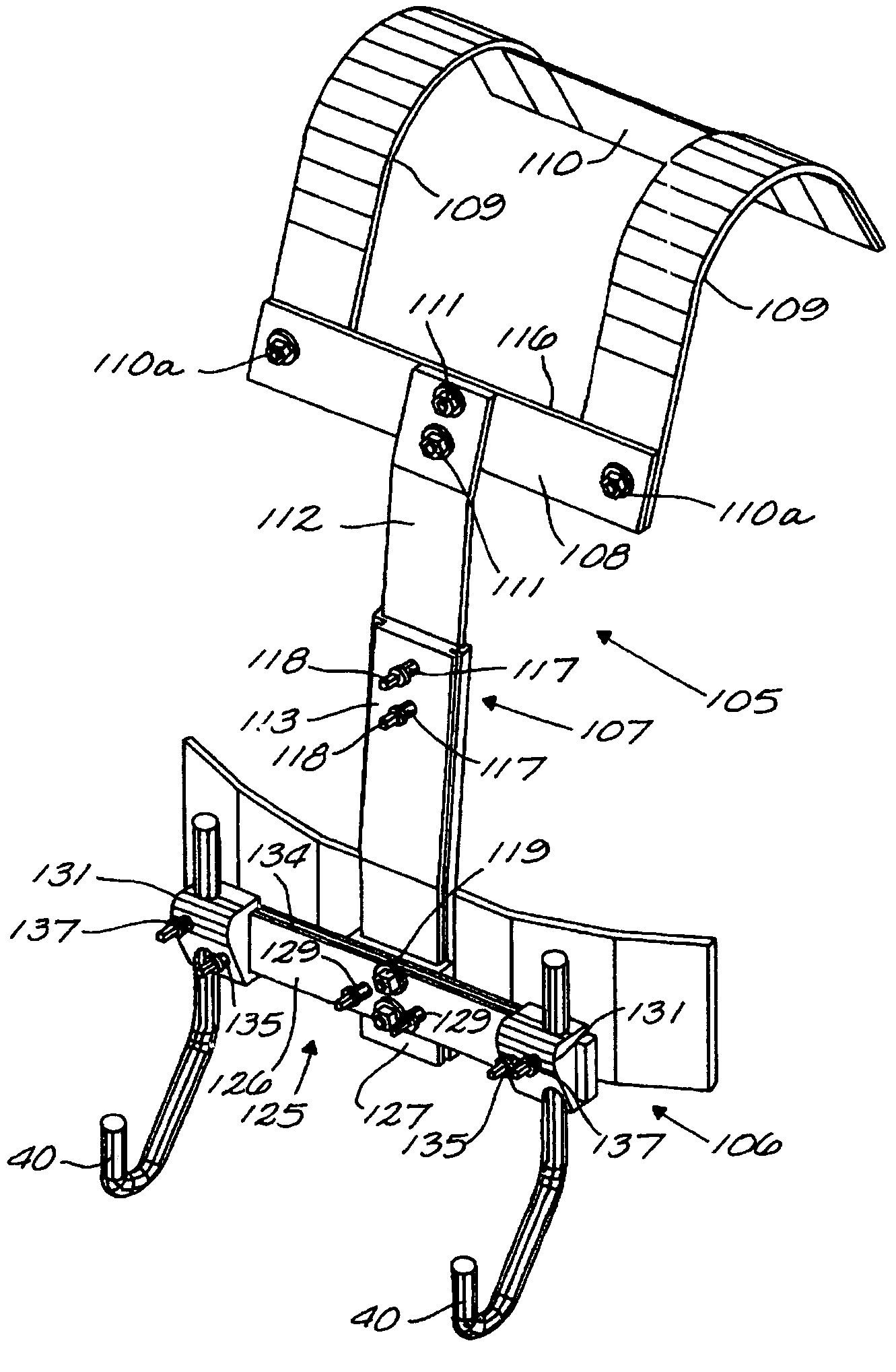
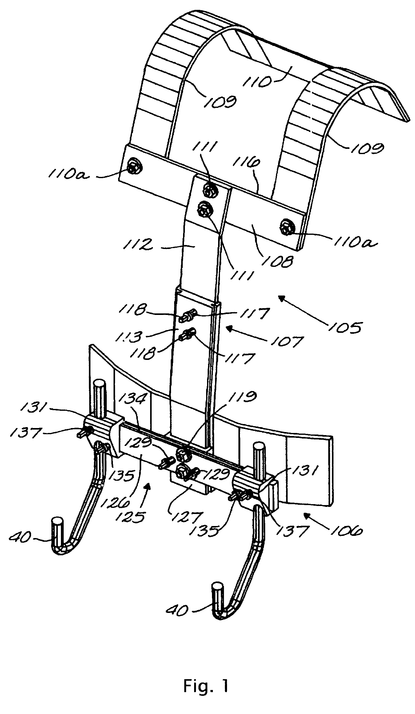
[0045]Referring to FIGS. 1-9, there is shown a T-bar-type carrier of the type shown which has been modified to provide almost universal adjustment of the points of attachment and location of the percussion instruments. Pads corresponding to the pads 104 on shoulder straps 109 / 148 used to cushion the load of the instruments carried by the carrier.

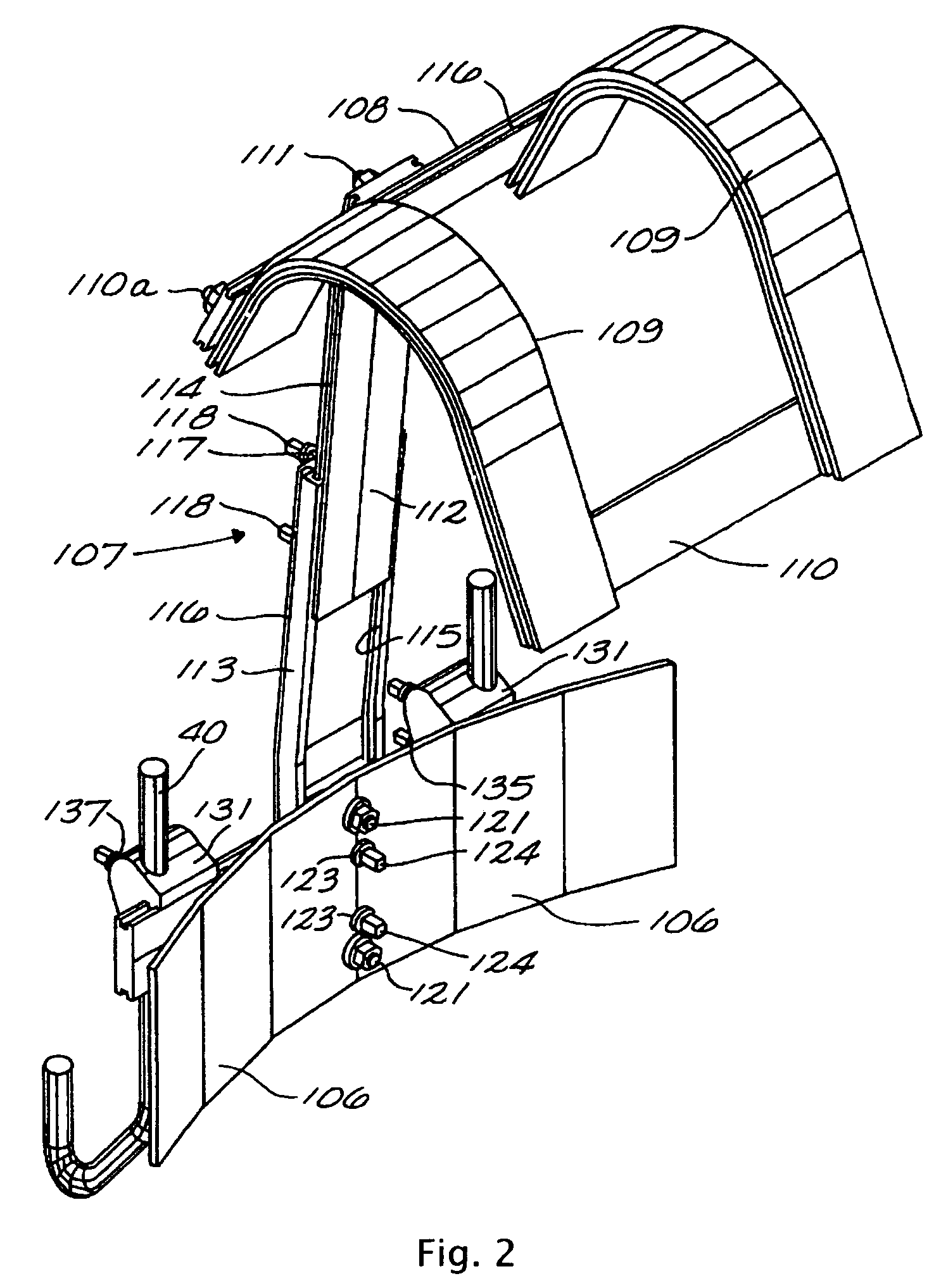
[0046]Adjustable carrier 105 (FIG. 1) for percussion instruments comprises a belly plate 106, vertical bar assembly 107, upper horizontal bar 108, shoulder straps 109 and back bar 110. Back bar 110 is removably secured to shoulder straps 109 by screws or bolts. Upper horizontal bar 108 is removably secured to shoulder straps 109 by bolts 110a. Upper horizontal bar 108 is removably secured to the upper end of vertical bar assembly 107 by bolts 111. Upper horizontal bar 108 has grooves 116 in the upper and lower edges for receiving adjustable sliding ...


PUM


Abstract

Drum hardware and drum secured thereon are preferably supported on a vest type carrier or a T-bar carrier having a plurality of separate parts removable from each other and formed of a rigid plastic, light metal such as magnesium, aluminum or titanium. The removable hardware includes a removable back support member. The instrument carrier includes an expandable and or adjustable front section(s) that allows for at least one front adjustment of the carrier to adjust the overall length of the carrier to accommodate users of different sizes.

Description

CROSS REFERENCE TO RELATED APPLICATION[0001]This application is a continuation-in-part of parent application Ser. No. 08 / 588,244, filed Jan. 18, 1996 now U.S. Pat. No. 5,691,492, which is a continuation-in-part of U.S. patent application Ser. No. 08 / 976,999 filed Nov. 24, 1997, now U.S. Pat. No. 6,028,257 which is a divisional application of U.S. patent application Ser. No. 09 / 497,266 filed Feb. 3, 2000 now U.S. Pat. No. 6,329,583 which is a continuation-in-part of U.S. patent application Ser. No. 09 / 756,479 filed Jan. 8, 2001 now U.S. Pat. No. 6,403,869 which is a continuation-in-part of U.S. patent application Ser. No. 10 / 170,005, filed Jun. 10, 2002, now U.S. Pat. No. 6,770,805 which is a continuation-in-part of U.S. patent application Ser. No. 10 / 374,676 filed Feb. 26, 2003 now U.S. Pat. No. 7,071,401 which is a continuation in part of U.S. patent application Ser. No. 10 / 831,638 filed Apr. 23, 2004, now U.S. Pat. No. 6,881,886 which is a continuation in part of U.S. patent appli...

Claims


Application Information

Patent Timeline
Patent Type & Authority Patents(United States)
IPC IPC(8): G10D13/02G10D13/00G10G5/00
CPCG10G5/005G10D13/00G10D13/28
Inventor MAY, RANDALL L
Owner RANDALL MAY INT
Why Eureka
Try Eureka