Method and apparatus for selective engagement of shelf divider structures within a shelf management system

a shelf management system and divider technology, applied in the field of retail display divider structures, can solve the problems of limiting the ability of store personnel to conveniently move, change or restock the merchandising display scheme, display is prone to disorganization, and not allowing convenient repositioning, etc., to achieve convenient fabrication, save time and labor costs, and simple use

Inactive Publication Date: 2008-07-08
MERIT JO A & WILLIAM
View PDF154 Cites 183 Cited by
  • Summary
  • Abstract
  • Description
  • Claims
  • Application Information

AI Technical Summary

Benefits of technology

[0004]Accordingly, one purpose and object of this invention is to overcome the shortcomings of the prior art by providing a latching and locking mechanism for a divider structure, a combination divider and spring urged pusher structure, or a divider base, which allows convenient engagement, release and re-engagement of the relevant structure to a mounting member that is securable to the front edge of a shelf without necessitating removal of the displayed articles from the shelf, thus saving on the time and expense of labor to perform this function.
[0005]In one embodiment, a latching and locking mechanism is provided that is simple in use and convenient in fabrication. This latching and locking mechanism holds the divider and / or base structure in place relative to the mounting member and thus prevents lateral movement of the divider and / or base structure along the mounting member attached to the shelf.
[0007]This invention allows shelves to be placed close, one above the other, in a store thereby to obtain maximum display area for the display of products to be sold while at the same time allowing the widths of the articles to be displayed to be adjusted without having to physically remove the divider structures from the shelves. As a feature of this invention, it is possible to reposition a divider laterally along a shelf merely by pressing down on a resilient extension (i.e. a resilient “latch”) from the divider base to unlock the base from the mounting member, push back on the divider to remove the latch from a slot in the mounting member, slide the divider and base laterally left or right along the shelf until the new position of the divider is reached, and then pull the divider and base forward to reinsert the latch from the base into a slot on the mounting member and cause a protrusion on the extension from the base to catch (i.e. lock) against another protrusion on a surface of the slot in the mounting member. Consequently, a divider can be repositioned along a shelf without having to lift the divider vertically. This means that the bottom of the shelf above the divider can be very close to the top of the divider and yet not interfere with the repositioning of the divider along the shelf. This allows the divider to be repositioned with minimum time and effort and without removing the articles stored adjacent the divider and allows more articles to be displayed in a given area.

Problems solved by technology

Moreover, generally sellers desiring to maximize product sales have increased the number of articles displayed within a given space, thereby significantly limiting the ability of store personnel to conveniently move, change or restock the merchandising display scheme.
Consequently, as articles are emptied from the shelf the display is prone to disarray.
The teeth lock the divider in place, but do not allow for conveniently repositioning the divider absent removing the displayed articles and the dividers from the shelf.
This is inconvenient, labor intensive and expensive for stores because even the slightest adjustment can require removing the articles from the shelf to reposition the dividers, then reloading the articles.

Method used


Image

  • Method and apparatus for selective engagement of shelf divider structures within a shelf management system
  • Method and apparatus for selective engagement of shelf divider structures within a shelf management system
  • Method and apparatus for selective engagement of shelf divider structures within a shelf management system

Examples


Embodiment Construction

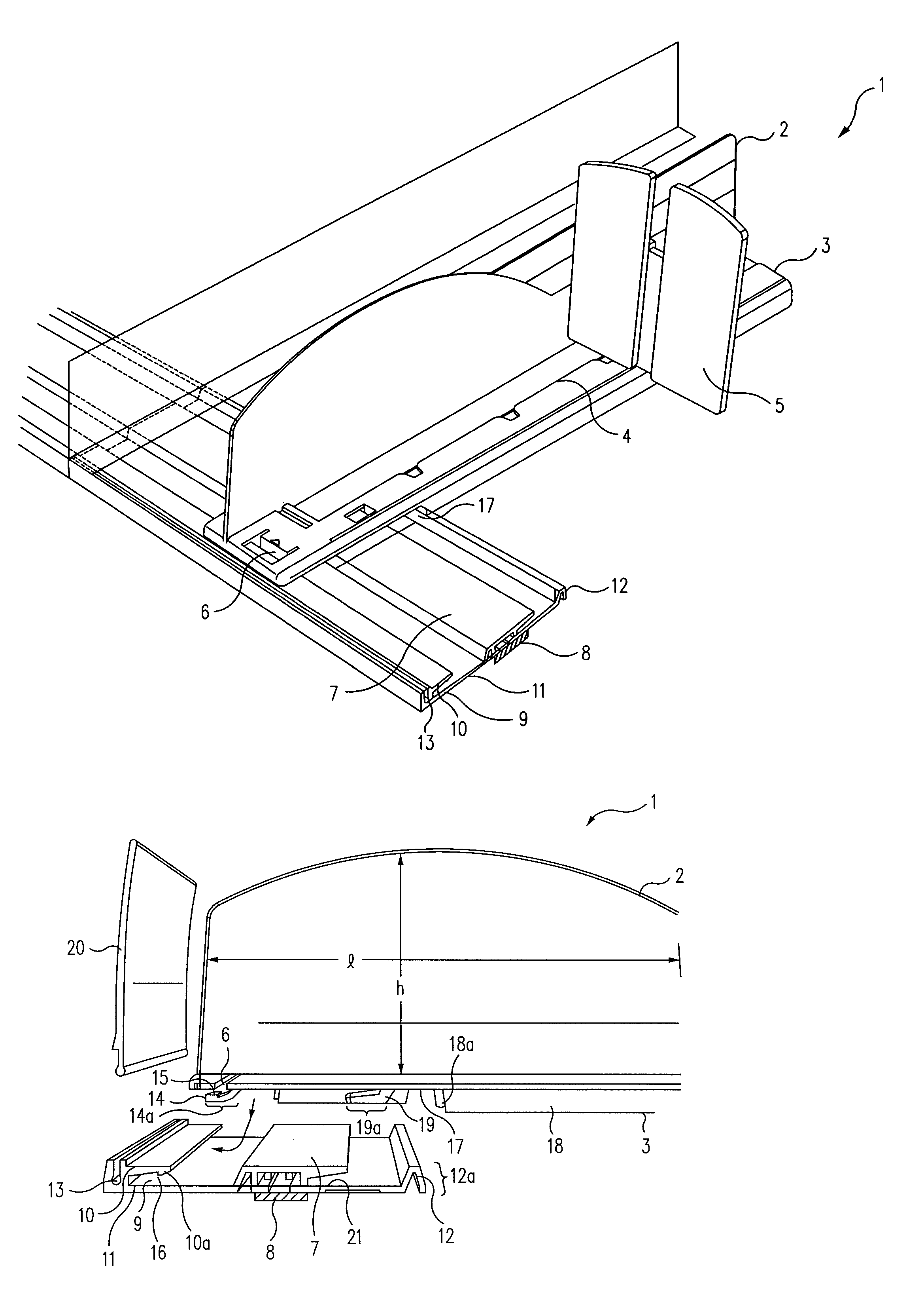
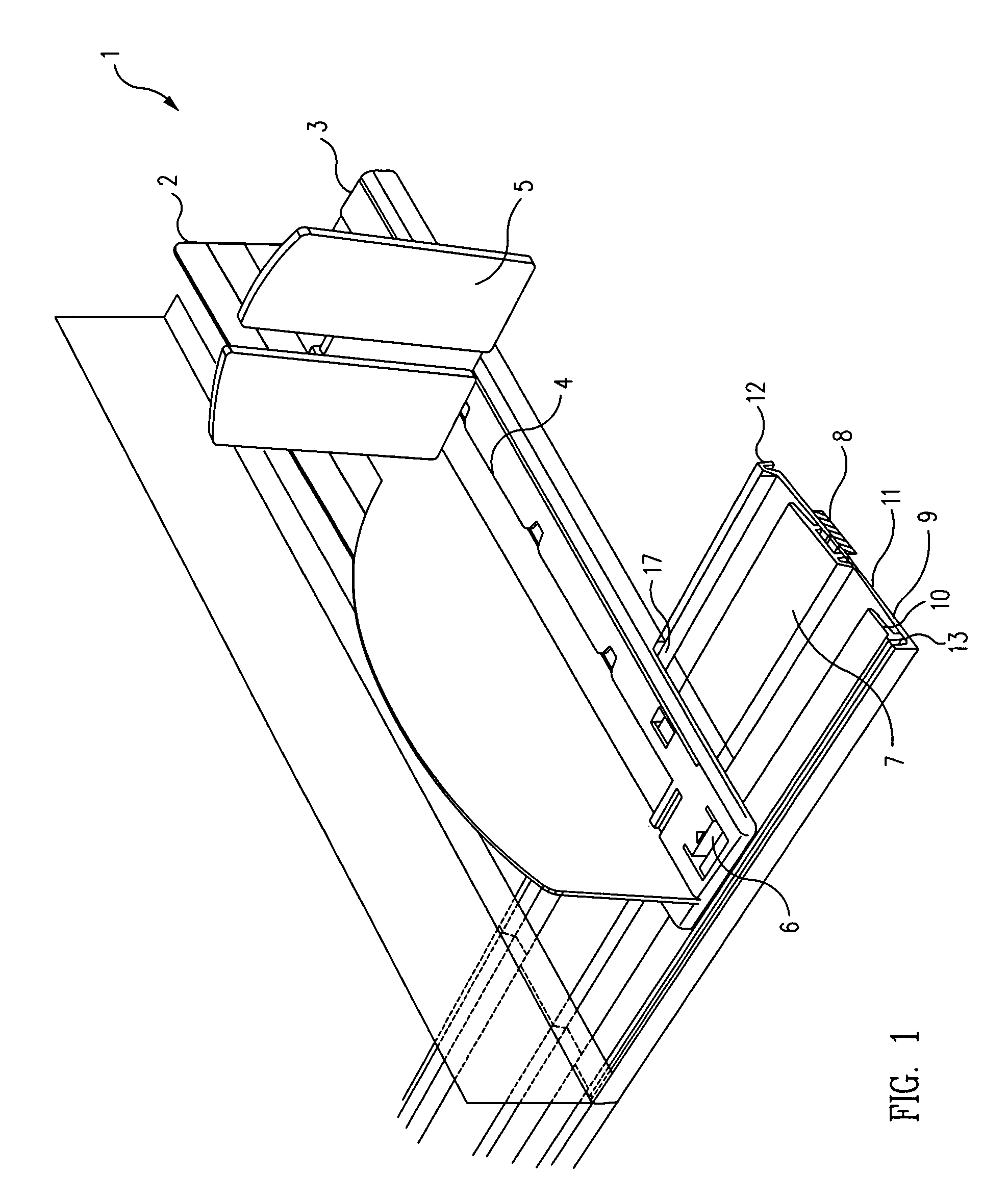
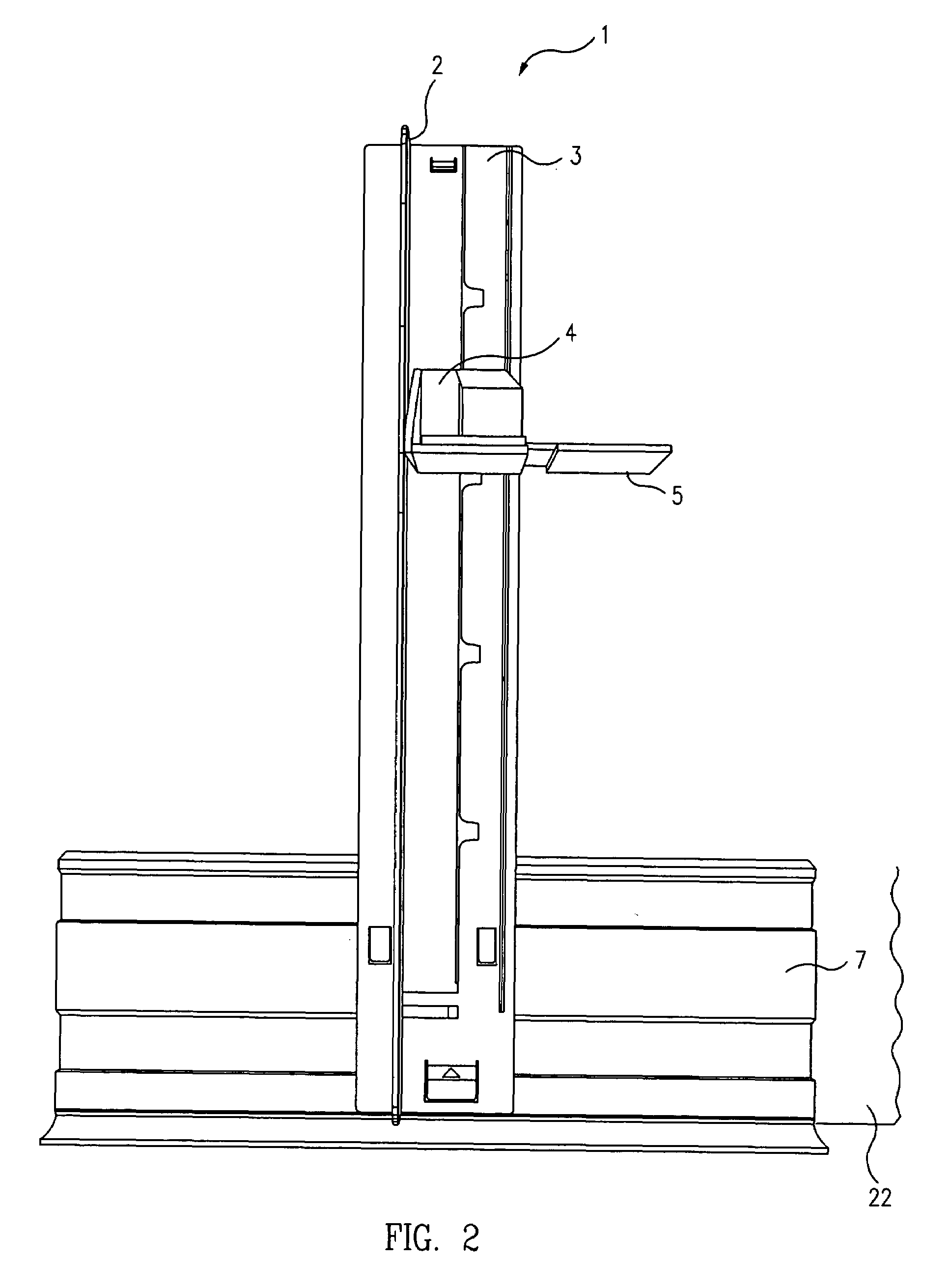
[0020]Referring now to the drawings, shown are several illustrative, but not limiting, embodiments of the divider structure of the shelf management system according to the present invention.

[0021]FIGS. 1 and 4 show a first embodiment of a divider system 1, comprising a vertical divider wall 2, and horizontal divider base 3. The terms “vertical” and horizontal” are used herein to illustrate the relative orientation of system components in the figures but it should be understood that in use these components may be oriented on shelves which slope and thus are other than perfectly horizontal. Base 3 includes an “L” shaped extension (sometimes called a latch 14) with a protrusion 15 (not shown in FIG. 1 but shown in FIG. 4) and a recess 17 (FIG. 4) which cooperatively engage with and lock onto a generally horizontal mounting member 7. Mounting member 7 is attached to a shelf (not shown for simplicity in FIGS. 1 and 3 through 7 but shown as 22 in FIG. 8). Member 7 includes a horizontal re...


PUM


Abstract

Apparatus and method for selectively engaging and securing an array of shelf dividers to a mounting device which is securable to a display shelf. In the first form a divider is characterized by a divider structure having an elongated vertical wall and elongated horizontal base that operates to divide, organize and support the displayed merchandise. A resilient latch located on the underside of the base of the divider structure selectively engages and secures the divider structure onto a mounting device comprising a receiving member running longitudinally along the length of the surface of the mounting device which is securable along the front edge of a display shelf. The latch and the receiving member each comprise reciprocating (i.e. complementary) protrusions to allow the cooperative engagement of the divider structure and mounting device, thus locking the divider member to and unlocking the divider member from the mounting device to permit the repositioning of the display as desired without necessitating removal of the merchandise from the display. In addition when the divider structure and mounting device are fully engaged, a second protrusion on the underside of the divider member cooperates with a flange or lip on the mounting device to prevent lateral movement of the divider structure and maintain the position of the divider perpendicular to the mounting device and the front edge of the shelf. In a second embodiment, the divider structure comprises a pusher track and a spring urged pusher assembly to automatically push merchandise to the front of the shelf. Another embodiment comprises a divider base without a vertical divider wall, and with or without a pusher track and spring urged pusher assembly, thus pushers and dividers can be used in various convenient combinations within a shelf management system.

Description

FIELD OF THE INVENTION[0001]The present invention relates to retail display divider structures and to a structure and method for conveniently securing same to store shelves. More particularly, this invention relates to retail display structures which may be easily reorganized without necessitating the removal of the retail merchandise from the display.BACKGROUND OF THE INVENTION[0002]In any merchandising scheme success in selling requires a constant modification of the goods offered for sale while maintaining a neatly organized display. The style, selection and assortment of goods in stores and the display mechanisms for displaying these goods are continuously changing. For these reasons, various prior art shelf organizing structures include the ability to rearrange the dividers within a display. Devices of this type are described in U.S. Pat. No. 5,690,038 issued Nov. 25, 1997, and U.S. Pat. No. 6,006,678 issued Dec. 28, 1999, to Merit. Merit teaches a divider structure that snaps ...

Claims


Application Information

Patent Timeline
Patent Type & Authority Patents(United States)
IPC IPC(8): A47F1/04
CPCA47F5/005A47F1/126
Inventor MERIT, JO A.HARLAN, JEFF L.
Owner MERIT JO A & WILLIAM
Why Eureka
Try Eureka