Childproof gate lock

a gate lock and childproof technology, applied in the field of gate locks, can solve the problems of ineffective protection of children or pets by gates, and achieve the effect of locking the gate more securely and safely

Active Publication Date: 2008-07-08
CHENG SHU CHEN
View PDF13 Cites 6 Cited by
  • Summary
  • Abstract
  • Description
  • Claims
  • Application Information

AI Technical Summary

Benefits of technology

[0008]A gate is mounted in a frame, which can be mounted in a doorway. The gate lock is mounted on the gate and the bolt assembly of the gate lock is mounted on the frame. When the gate is closed, the bolt is engaged in the slot in the lock core. The lock core is then rotated 90 degrees. The bolt will not slide out of the slot, and the gate is locked. To unlock the gate, the lock core is rotated 90 degrees in the opposite direction. The gate is then lifted upward allowing the bolt to slide out of the slot, thus enabling the gate to swing open. The design of this invention has two locking mechanisms that can lock the gate more securely and safely than the prior art.

Problems solved by technology

However, the gates are usually secured with simple latches or locking devices, which can be easily opened by some smart children, thus rendering the gates ineffective in protecting children or pets.

Method used


Image

  • Childproof gate lock
  • Childproof gate lock
  • Childproof gate lock

Examples


Embodiment Construction

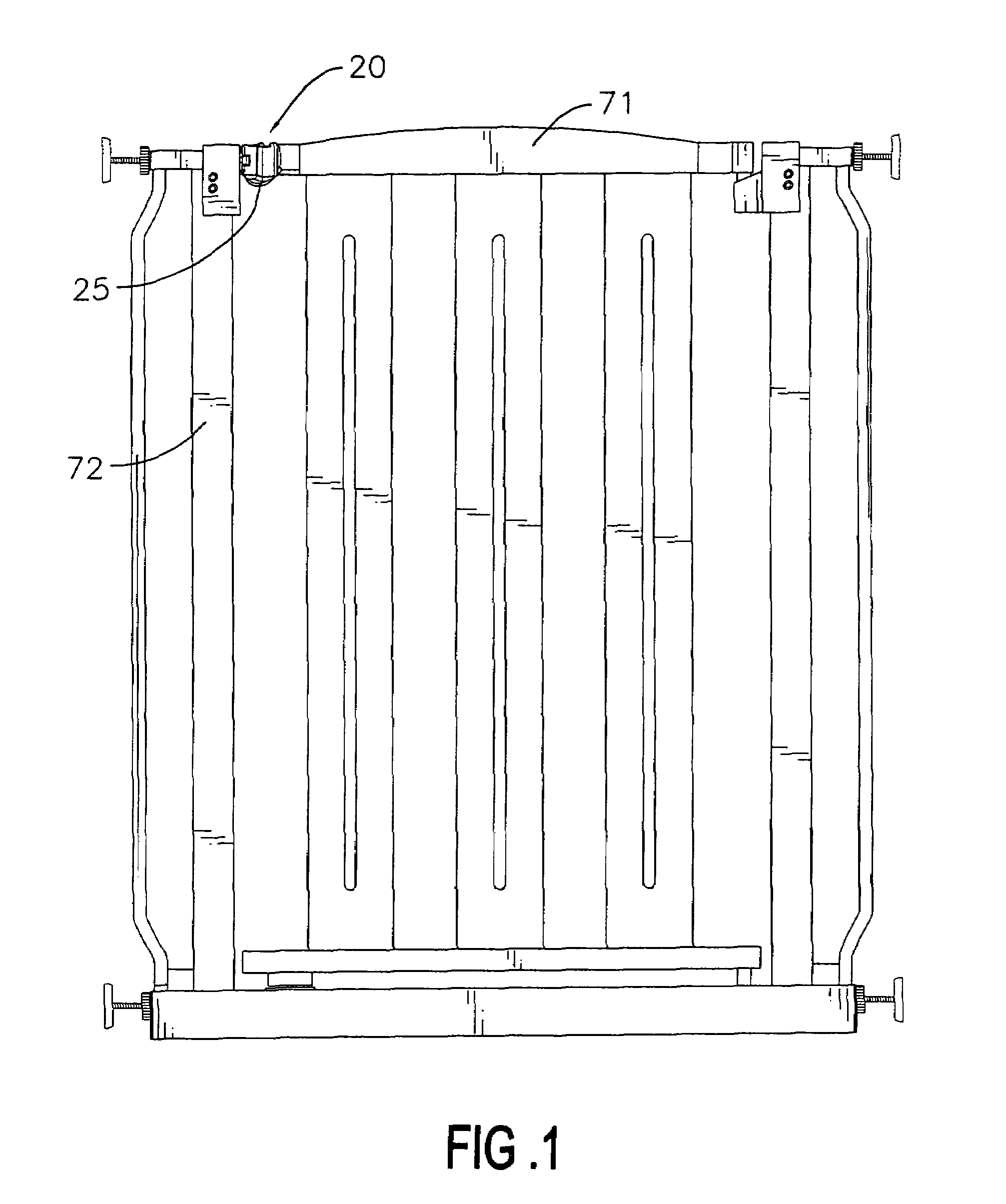
[0020]With reference to FIG. 1, a gate (71) is mounted on a frame (72) that is mounted in a doorway. The gate (71) has a top rail with an end pivotally mounted on the frame (72), while a gate lock (not numbered) is mounted on an opposite end.

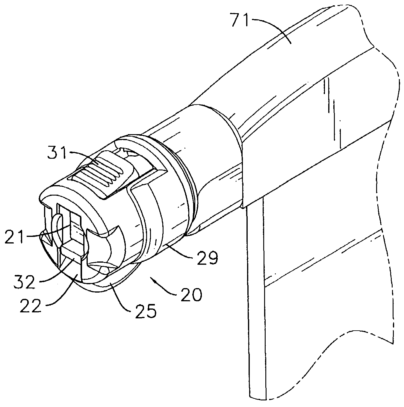
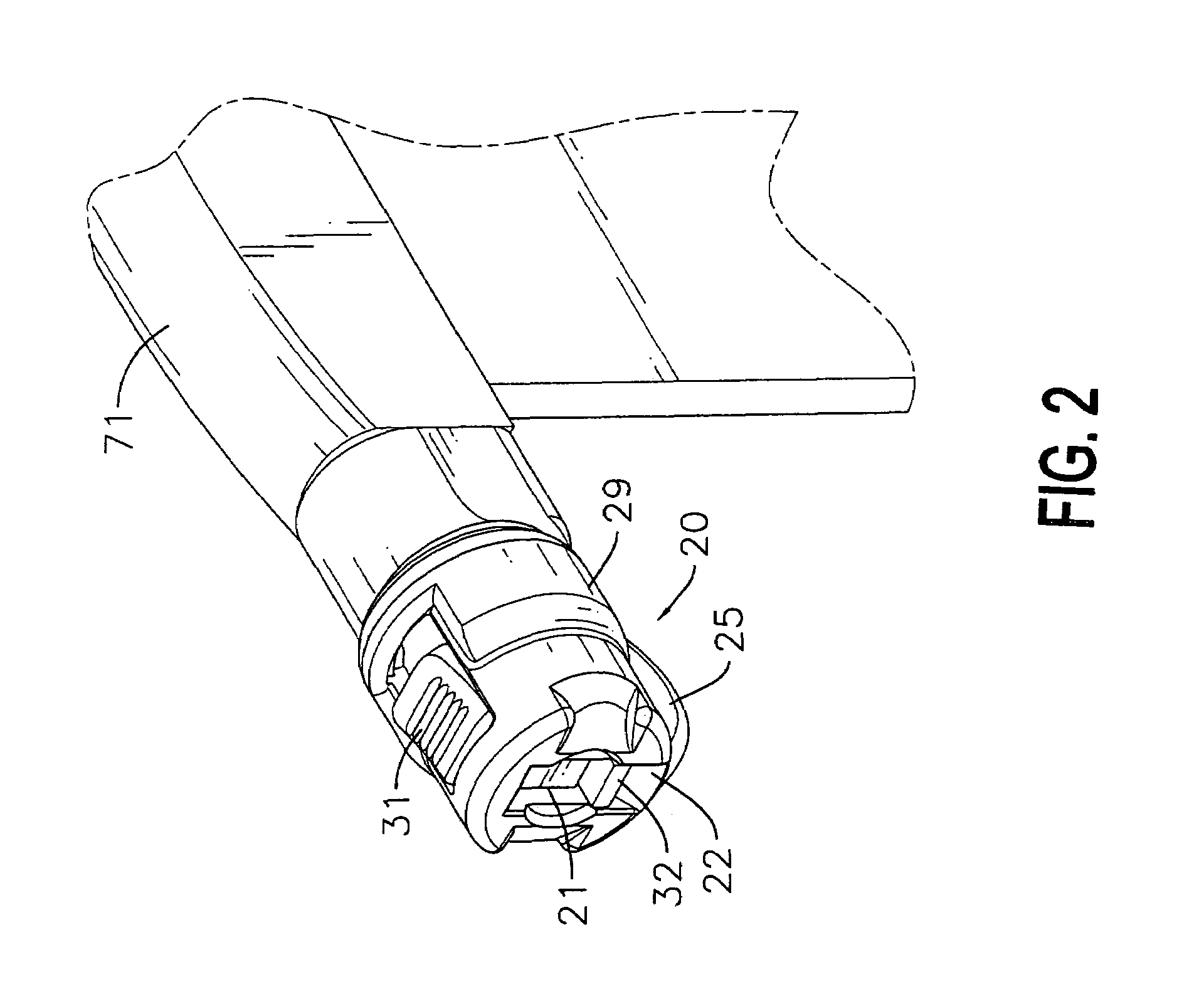
[0021]With reference to FIGS. 2-5, the gate lock is comprised of a lock base (10), a lock core (20) with a slot (21) defined therein, a latch member (30) and a bolt assembly (50).

[0022]The lock base (10) is a hollow cylinder with two ends and has a bottom and a top. The lock base (10) is mounted on an end of the top rail of the gate (71). A cylindrical protrusion (13) extends from one end of the lock base (10) and has multiple lugs formed at an end. An annular member (12) is formed around the protrusion (13) and has a stop (14) extending outward from an edge near the bottom of the lock base (10). A first curved rail (15) is defined along an inner wall of the annular member (12) in a space between the annular member (12) and the protrusion (13).

[...


PUM


Abstract

A gate lock is composed of a lock base, a lock core with a slot defined therein, a latch member and a bolt assembly. A gate is mounted in a frame, which can be mounted in a doorway. The gate lock is mounted on the gate and the bolt assembly of the gate lock is mounted on the frame. When the gate is closed, the bolt is engaged in the slot in the lock core. The lock core is then rotated 90 degrees. The bolt will not slide out of the slot, and the gate is locked. To unlock the gate, the lock core is rotated 90 degrees in the opposite direction. The gate is then lifted upward allowing the bolt to slide out of the slot, thus enabling the gate to swing open.

Description

BACKGROUND OF THE INVENTION[0001]1. Field of the Invention[0002]The present invention relates to a gate lock, and particularly relates to a gate lock mounted on a gate or barrier to prevent children or pets from getting out.[0003]2. Description of the Related Art[0004]Little children normally lack an awareness of danger. They may wander out of a room or a home without parents noticing. Pets can also get out easily if there are no restrictions. Gates or barriers are usually mounted in doorways to prevent small children or pets from getting out.[0005]However, the gates are usually secured with simple latches or locking devices, which can be easily opened by some smart children, thus rendering the gates ineffective in protecting children or pets.[0006]Therefore, the invention provides a gate lock to mitigate or obviate the aforementioned problems.SUMMARY OF THE INVENTION[0007]The main objective of the present invention is to provide a gate lock that is childproof. A gate lock in accord...

Claims


Application Information

Patent Timeline
Patent Type & Authority Patents(United States)
IPC IPC(8): E05B15/02E05C1/08
CPCE06B9/00E06B2009/002Y10T292/0969Y10T292/696
Inventor CHENG, SHU-CHEN
Owner CHENG SHU CHEN
Why Eureka
Try Eureka