Industrial Truck With Load Rollers Located On Load Roller Carriers On A Wheelarm

Inactive Publication Date: 2014-06-19
STILL SPA
View PDF13 Cites 3 Cited by
  • Summary
  • Abstract
  • Description
  • Claims
  • Application Information

AI Technical Summary

Benefits of technology

[0012]If the load roller carrier has two lateral bearing levers, in each of which there is an outer bushing or bearing eye for the bearing pin, the at least one roller is advantageously located between the bearing levers. With a location of the rotatable rollers between the two lateral bearing levers of the load roller carrier, a central location of the at least one roller with reference to the wheelarm in the transverse direction of the vehicle can be achieved. This makes possible an easy insertion of the wheelarms into the pickup openings of the pallet.
[0013]It is particularly advantageous if the bearing pin is supported in alteration in a bearing eye of the wheelarm and a bearing eye of the load roller carrier. It is also advantageous if a roller is located in the longitudinal direction of the bearing pin between the bearing eye of the wheelarm and the bearing eye of the load roller carrier. With a location of this type of the bearing eyes in the wheelarm and the load roller carriers, the bearing pin can be supported at more than two bearing points on the wheelarm. This makes it possible to reduce the diameter of the bearing pin without the danger of deflection or deformation of the bearing pin and to achieve low loads caused by the forces exerted on it, as a result of which a low height of the wheelarms in the lowered position becomes possible. The location of a plurality of rollers each between a bearing eye of the wheelarm and a neighboring bearing eye of the load roller carrier results in a simple construction and a simple bearing system for the rollers and facilitates the insertion of the wheelarms into the pickup openings of the pallet in a particularly effective manner.
[0014]It is particularly advantageous if the load roller carrier has two outer bearing eyes and a center bearing eye for the bearing pin. One bearing eye of each wheelarm is located between the center bearing eye and the outer bearing eye of the respective load roller carrier and a roller is each located between the bearing eye of the wheelarm and the center bearing eye and the outer bearing eye of the load roller carrier. With an additional center bearing eye for the bearing pin on the load roller carrier and additional bearing eyes for the bearing pin on the wheelarm, each of which is located between the center bearing eye and the outer bearing eye of the load roller carrier, it is possible to achieve a secure mounting of the bearing pin. This makes possible a particularly effective reduction of the diameter of the bearing pin, which in turn makes it possible to achieve a low height of the whe

Problems solved by technology

Thus, when the wheelarms are inserted, a great deal of friction occurs under the pallet and, therefore, a great deal of force is required to push the wheelarms into the pallet.
Under some conditions, the pallet can be damaged.
Damage can occur in p

Method used


Image

  • Industrial Truck With Load Rollers Located On Load Roller Carriers On A Wheelarm
  • Industrial Truck With Load Rollers Located On Load Roller Carriers On A Wheelarm
  • Industrial Truck With Load Rollers Located On Load Roller Carriers On A Wheelarm

Examples


Embodiment Construction

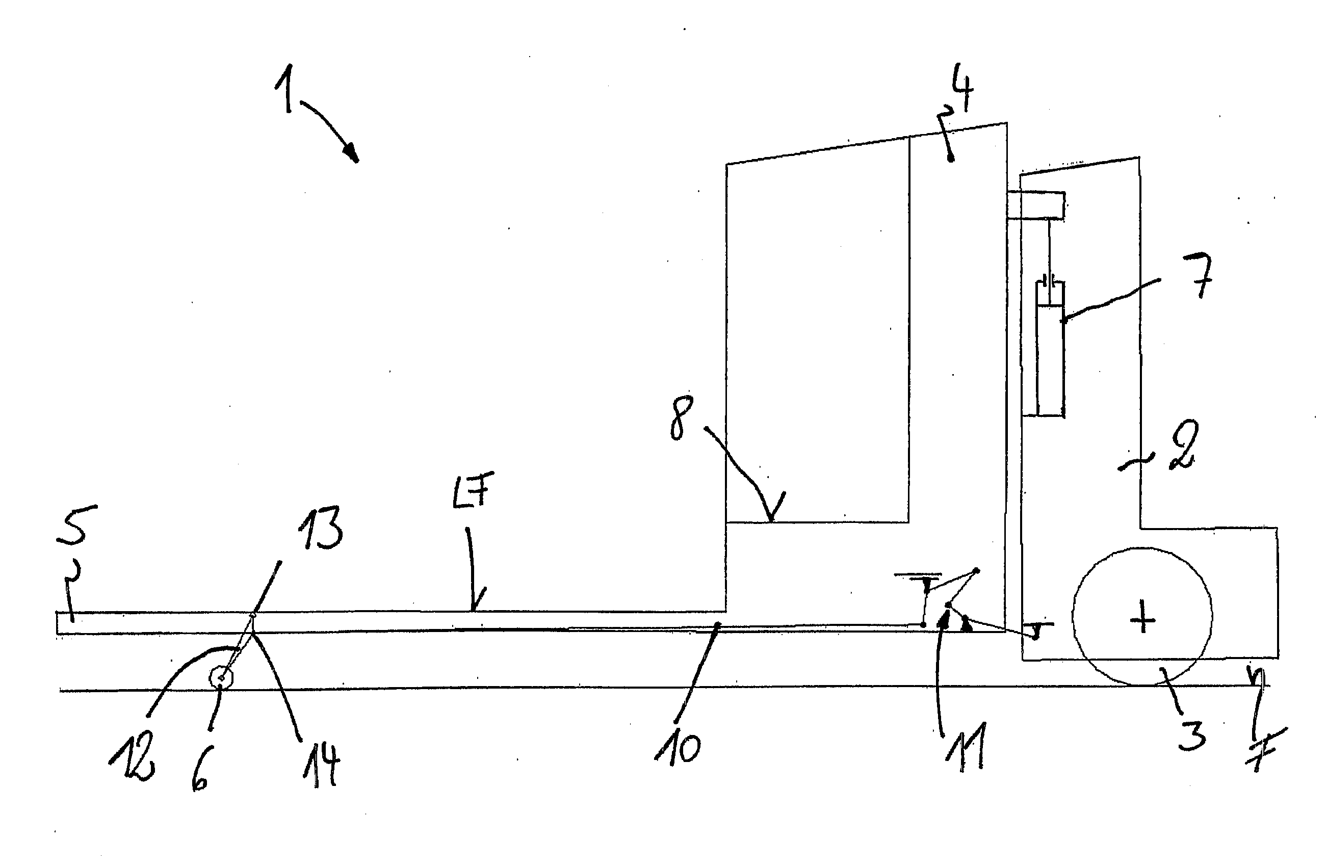
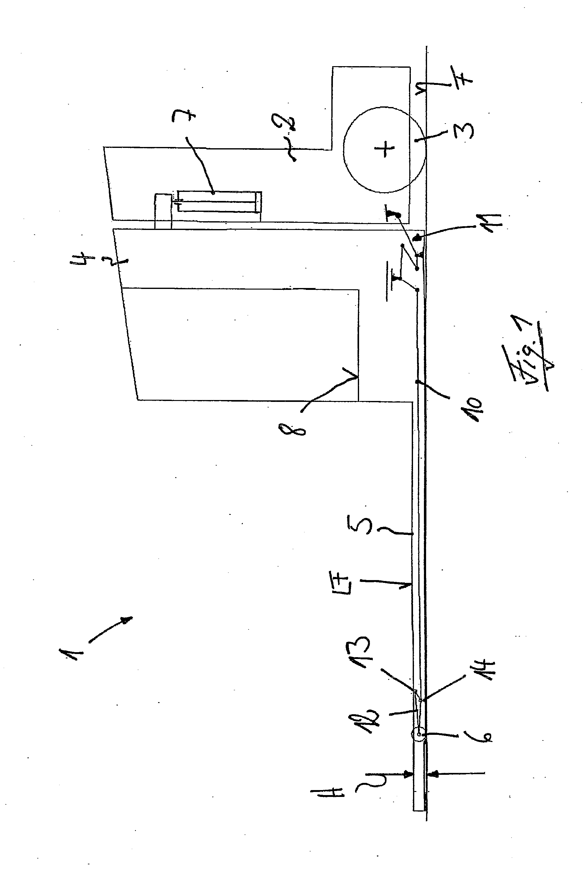
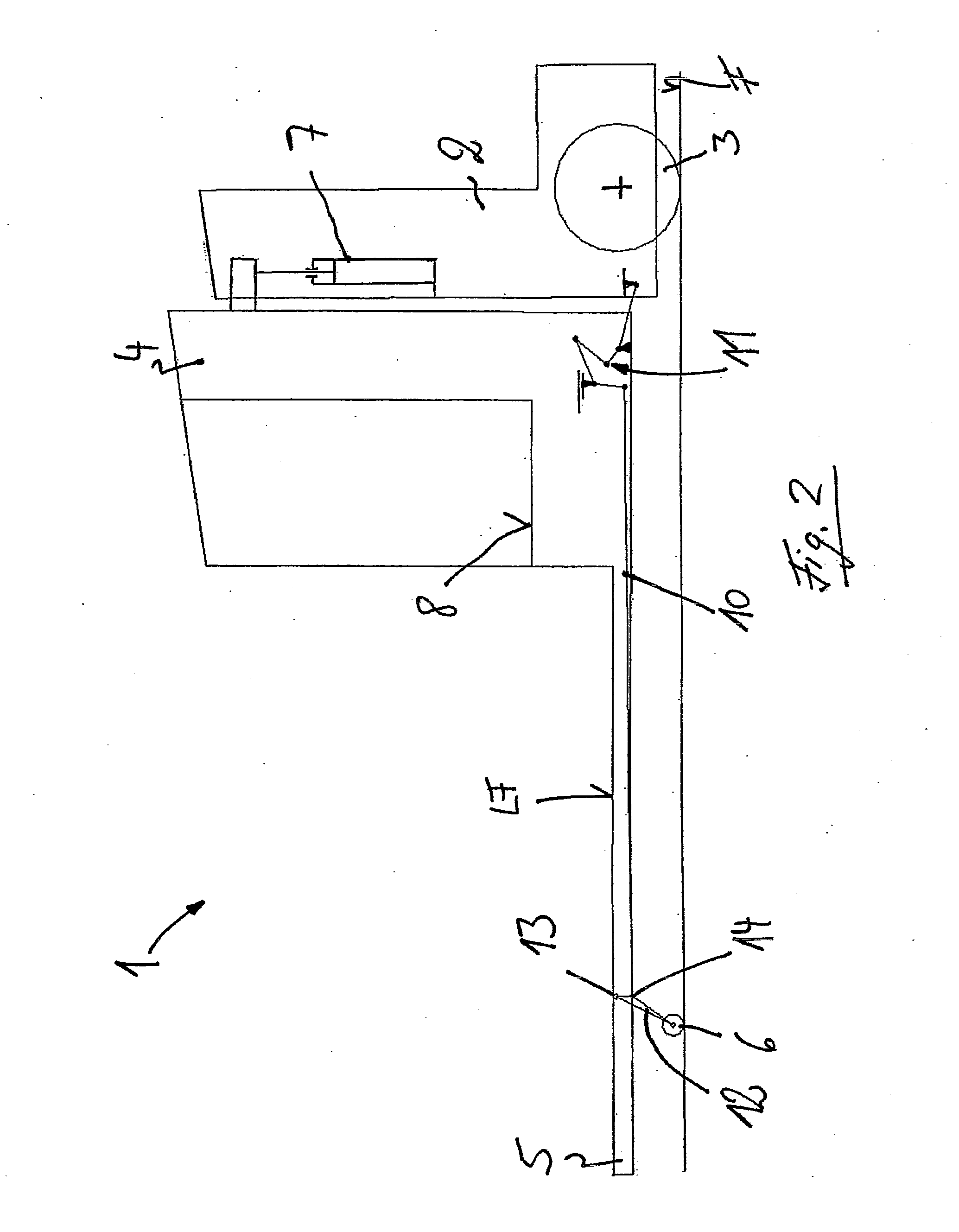
[0025]The industrial truck 1 illustrated in a side view in FIGS. 1 and 2, such as a lift truck in the form of a low-lift truck or a high-lift truck, for example, has a drive section 2 provided with a steerable drive wheel 3, and a load section 4 which can be raised and lowered relative to the drive section 2. The load section 4 preferably comprises two wheelarms 5 which are at a spaced lateral distance from each other and are supported on a roadway F by load rollers 6 which are located at or near the tip of the respective wheelarm 5. The drive section 2 is supported on the roadway F by the drive wheel 3. To increase stability, the drive section 2 can be supported on the roadway F by support rollers, which are not illustrated in any further detail. The upper sides of the wheelarms 5 form a load-bearing surface LF, which can be driven under and lift a pallet, which is not illustrated in any further detail.

[0026]To raise the load section 4, a lifting device 7 is provided, which can inc...


PUM


Abstract

An industrial truck (1) has a drive section (2) and a load section (4) movable relative to the drive section (2). The load section (4) has at least one wheelarm (5) having at least one load roller (6). The load roller (6) is rotatably mounted in a load roller carrier (12) swively-mounted by a swivel bearing (13) on the wheelarm (5). In the vicinity of the swivel bearing (13), on the upper side of the wheelarm (5), there is an entry guide (20). The guide (20) includes at least one roller (21; 22; 23; 24) rotatably mounted on the wheelarm (5) and projecting upwardly beyond a load-bearing surface (LF) of the wheelarm (5). The swivel bearing (13) of the load roller carrier (12) includes a bearing pin (25). The at least one roller (21; 22; 23; 24) is rotatably mounted on the bearing pin (25).

Description

CROSS REFERENCE TO RELATED APPLICATIONS[0001]This application claims priority to German Applications DE 102012109789.5 filed Oct. 15, 2012 and DE 102013100468.7 filed Jan. 17, 2013, both of which are herein incorporated by reference in their entirety. This application is related to U.S. application Ser. No. ______ entitled “Industrial Truck With Wheelarm Lever System” and to U.S. application Ser. No. ______ entitled “Industrial Truck With Load Rollers Located In Swiveling Load Roller Carriers”, both filed concurrently herewith and both herein incorporated by reference in their entirety.BACKGROUND OF THE INVENTION[0002]1. Field of the Invention[0003]This invention relates to an industrial truck, in particular a lift truck, with a drive section and a load section that can be raised and lowered relative to the drive section. The load section has at least one wheelarm which is provided with at least one load roller. The load roller is mounted so that it can rotate in a load roller carri...

Claims


Application Information

Patent Timeline
IPC IPC(8): B66F9/065
CPCB62B3/0631B62B2203/20B66F9/065
Inventor MARIOTTI, FABIO
Owner STILL SPA
Why Eureka
Try Eureka