Heat exhaustion apparatus and image forming apparatus using same

a technology of heat exhaustion apparatus and image forming apparatus, which is applied in the direction of electrographic process apparatus, instruments, optics, etc., can solve the problems of uneven concentration of toner particles, difficulty in speeding up the forming of images, and increased size and cost of tandem types

Active Publication Date: 2008-07-15
RICOH KK
View PDF14 Cites 19 Cited by
  • Summary
  • Abstract
  • Description
  • Claims
  • Application Information

AI Technical Summary

Problems solved by technology

However, it is difficult to achieve speed-up in forming an image because a full color image must be formed through plural (generally four) image formations using only one image carrier.
On the other hand, the tandem type tends to be increased in size and cost because of plural imaging units arranged therein.
In sufficient charge of the toner causes toner particle scattering or concentration unevenness.
As a result, parts in the tandem type color image forming apparatus, therefore, heat exhaustion from the inside of the apparatus is a major issue.
As a result, the apparatus becomes tall and not convenient for all users to use.
As a result, since air heated inside the process cartridge cannot be exhausted efficiently, temperature inside the process cartridge cannot be reduced sufficiently.
Although a rotation speed of the exhaust fan can be increased to solve this problem, this increase power consumption.
However, since heated air rises, the heat exhaust duct disposed on the side face is inferior in suction efficiency compared to the heat exhaust duct disposed above a heat source, which is the process cartridge.
Therefore, it is difficult to sufficiently lower the temperature inside the process cartridge.
However, if the optical writing device is arranged just above the imaging unit, a space above the imaging unit is partially closed by a frame plate on which the optical writing device is mounted, so that a space above the imaging unit is limited.
When a duct for heat exhaustion is disposed in the limited small space, workability becomes poor for a general method such as a screwing work, and powder dust due to screwing (metal or resin debris) is generated or a distal end of a projecting screw abuts on an attachable and detachable imaging unit.
In JP-A No. 2004-205999, since interior of the apparatus is densely arranged and routes for heat exhaustion are reduced, it is difficult to effectively cool the imaging unit (developing device).
Particularly on a back side of the apparatus, effective cooling cannot be performed because heat is more likely to accumulate on the back side.

Method used


Image

  • Heat exhaustion apparatus and image forming apparatus using same
  • Heat exhaustion apparatus and image forming apparatus using same
  • Heat exhaustion apparatus and image forming apparatus using same

Examples


first embodiment

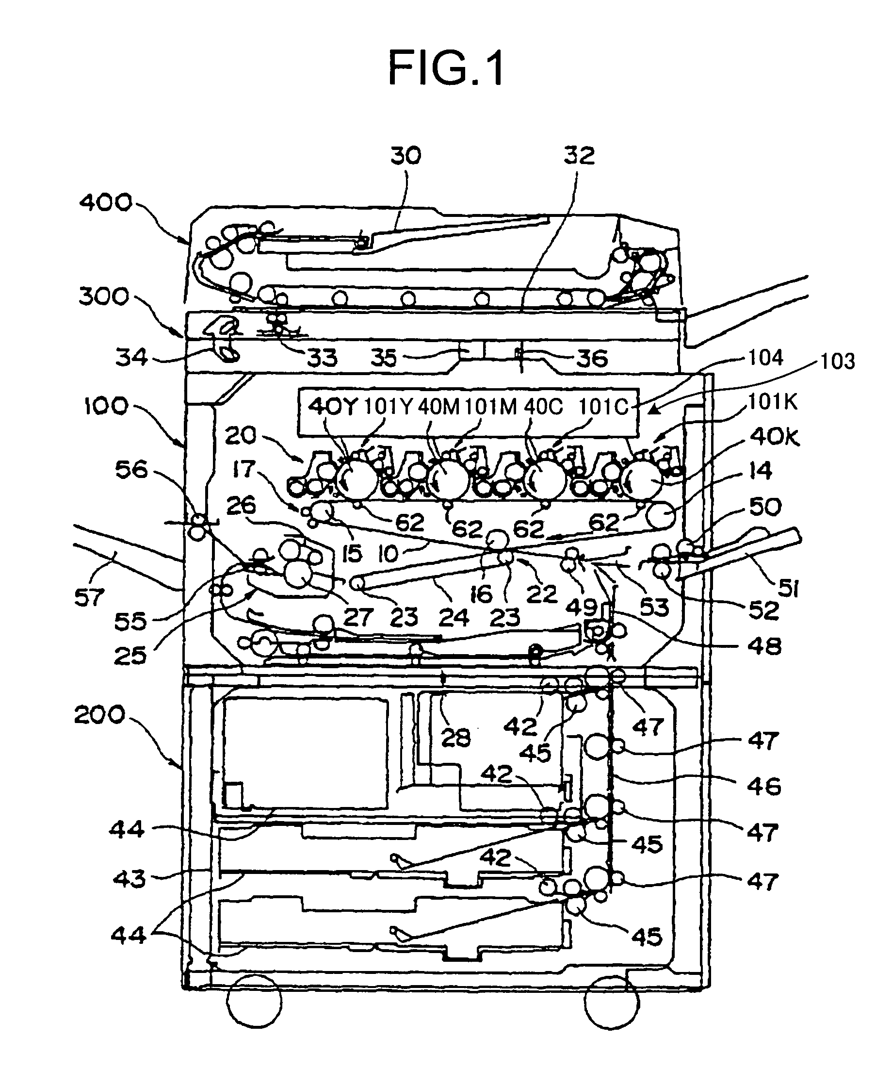
[0043]Exemplary embodiments according to the present invention will be explained in detail with reference to the accompanying drawings. FIG. 1 is a schematic of a copying machine according to the present invention. As shown in FIG. 1, the copying machine includes the main unit 100 and a paper feeding unit (a paper feed table) 200 on which the main unit is placed. Reference numeral 300 denotes a scanner mounted on the main unit 100, and reference numeral 400 denotes an automatic document feeder (ADF) provided above the scanner 300. The copying machine is an electrophotographic copying machine of a tandem type adopting an intermediate transfer (indirect transfer) system.

[0044]The main unit 100 includes an intermediate transfer belt 10 that is an intermediate transfer member serving as an image carrier at a central portion thereof. The intermediate transfer belt 10 is spanned around three supporting rollers 14, 15, and 16 serving as supporting and rotating members, and it is rotational...

second embodiment

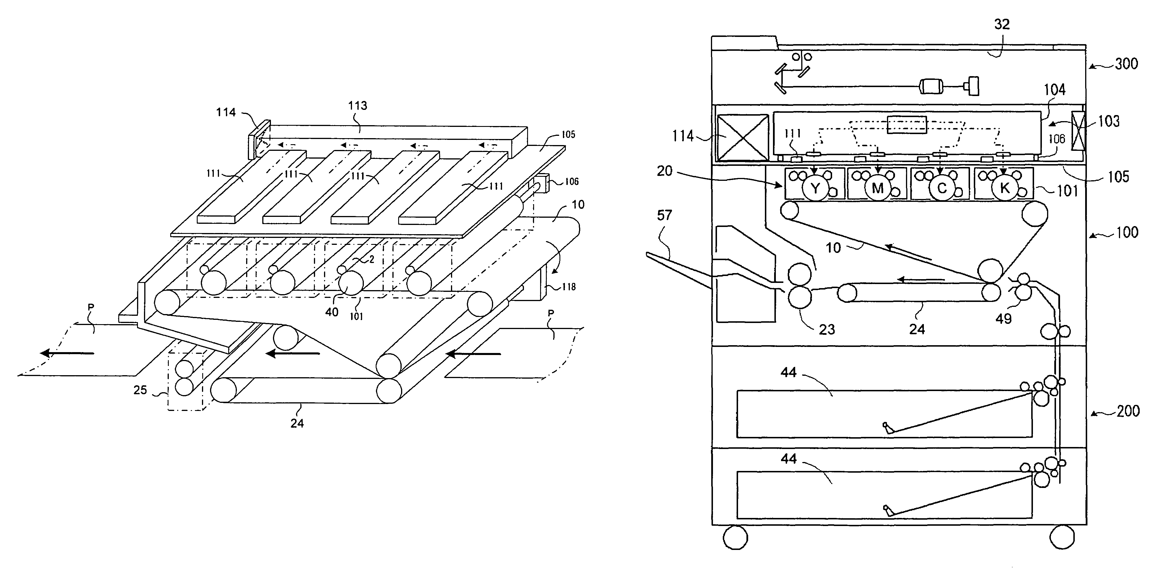
[0082]FIG. 11 is a plan view of the ducts in the copying machine according to the As shown in FIG. 11, the common duct 113 is provided to extend in a widthwise direction of the apparatus (left and right directions in FIG. 9 and FIG. 11) and it is connected to the exhaust fan 114 at one end thereof. Thus, when the exhaust fan 114 is rotated, hot air generated in the imaging unit 101 passes through the heat exhaust hole 110 provided in the unit frame 105 (arrow Z in FIG. 10) and passes through the common duct 113 from the heat exhaust duct 111 (arrows Y and X in FIG. 10) to be exhausted outside the copying machine by the exhaust fan 114. In the embodiment, heat generated in the imaging unit 101 mainly comes from self-heating at the developing unit (heat generated by friction occurring among developers in the developing element).

[0083]In a compact apparatus adopting a tandem system in which a plurality of (four) imaging units are arranged in parallel and the optical writing device 103...

third embodiment

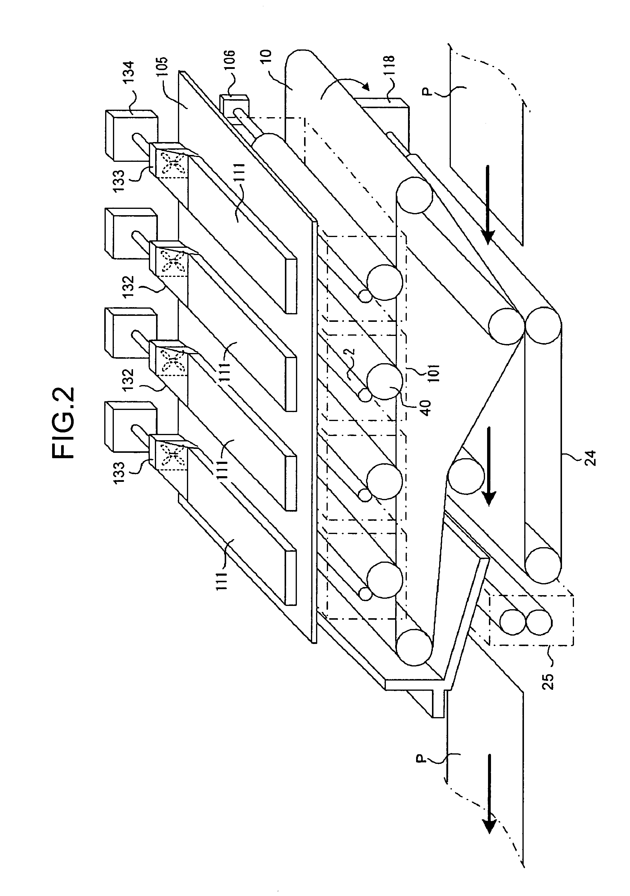
[0109]According to the copying machine of the third embodiment, a vertical sectional shape of the heat exhaust duct 111 for exhausting heated air within each imaging unit 101 is set such that a horizontal length thereof is longer than a vertical length thereof. Specifically, the heat exhaust duct 111 has a vertical sectional shape in which a height thereof is 5 millimeters or less and a vertical sectional area thereof is 100 square millimeters or more.

[0110]Thus, the heat exhaust duct 111 can be set to have a sectional area (100 square millimeters or more) that allows suction of a sufficient amount of heated air for lowering temperature inside the imaging unit 101 while suppressing the height of the heat exhaust duct 111. As a result, the arrangement position of the optical writing device 103 can be suppressed from being higher than that in the conventional image forming apparatus, and the temperature inside the imaging unit 101 can be lowered sufficiently. The heat exhaust ducts 11...


PUM


Abstract

Heat exhaust holes are provided in a unit frame at positions just above respective imaging units. An exhaust fan causes air heated at developing elements to be exhausted outside an apparatus via heat exhaust ducts and a common duct. The heat exhaust holes are formed in different sizes depending on a position of the imaging unit. The closer the position of the imaging unit is, the larger the heat exhaust hole provided above the imaging unit is.

Description

CROSS-REFERENCE TO RELATED APPLICATIONS[0001]This application is based upon and claims the benefit of priority from Japanese Patent Application Nos. 2004-331143, 2004-331144, and 2004-331270, filed Nov. 15, 2004, the entire contents of which are incorporated herein by reference.BACKGROUND OF THE INVENTION[0002]1. Field of the Invention[0003]The present invention relates to a technology for exhausting heat from a developing device in an image forming apparatus.[0004]2. Description of the Related Art[0005]Recently, in an image forming apparatus utilizing an electrophotographic system, apparatuses that can form a color image, such as a color copying machine and a color printer, are increasing to meet a demand from the market. As the color image forming apparatus, there are a one drum type and a tandem type. In the one drum type, plural developing elements are arranged around one image carrier (photosensitive element). In the tandem type, plural imaging units are arranged in parallel.[0...

Claims


Application Information

Patent Timeline
Patent Type & Authority Patents(United States)
IPC IPC(8): G03G21/20
CPCG03G15/0194G03G21/206G03G2221/1678G03G2221/18
Inventor TAKEHARA, KENICHIIIJIMA, YASUAKITAKIGAWA, JUNYASUGA, TOMOAKI
Owner RICOH KK
Why Eureka
Try Eureka