Wheelchair, wheel for wheelchair, and method of producing wheel for wheelchair

a technology for wheelchairs and wheel chairs, which is applied in the direction of wheelchairs/patient conveyances, hand carts with one axis, transportation and packaging, etc. it can solve the problems of high cost of a drive wheel of the conventional example 3, heavy large burden on the carer, so as to reduce the weight of the wheel, reduce the number of rolling elements, and ensure the effect of safety

Inactive Publication Date: 2008-07-22
THK CO LTD
View PDF17 Cites 0 Cited by
  • Summary
  • Abstract
  • Description
  • Claims
  • Application Information

AI Technical Summary

Benefits of technology

[0007]The drive wheel of the conventional example 3 has an advantage that clothes are not rubbed and damaged even if the clothes contact the drive wheel since the inner peripheral side does not rotate. However, since the metallic wheels are doubled and a plurality of rollers are provided, the weight is heavy. In particular, a large force is required as a force to push the hand rims 56 when starting the wheelchair. Further, if the wheelchair itself is heavy, a large burden is placed on a carer, when the carer holds up the user on the wheel chair together with the wheelchair to walk up and down stairs or the like. In addition, the cost of a drive wheel of the conventional example 3 is high.
[0008]In view of the above, an object of the present invention is to provide a wheel for a wheelchair, a wheelchair itself, and a method of manufacturing a wheel for a wheelchair, in which the weight of the wheel is not heavy and the inner peripheral side of the wheel does not rotate.

Problems solved by technology

However, since the metallic wheels are doubled and a plurality of rollers are provided, the weight is heavy.
Further, if the wheelchair itself is heavy, a large burden is placed on a carer, when the carer holds up the user on the wheel chair together with the wheelchair to walk up and down stairs or the like.
In addition, the cost of a drive wheel of the conventional example 3 is high.
The rolling element is a part receiving the weight applied from the inner wheel to the outer ring (or from the outer ring to the inner ring), which is required to have a sufficient intensity, therefore it is difficult to make the rolling element itself lighter.

Method used


Image

  • Wheelchair, wheel for wheelchair, and method of producing wheel for wheelchair
  • Wheelchair, wheel for wheelchair, and method of producing wheel for wheelchair
  • Wheelchair, wheel for wheelchair, and method of producing wheel for wheelchair

Examples


embodiment 1

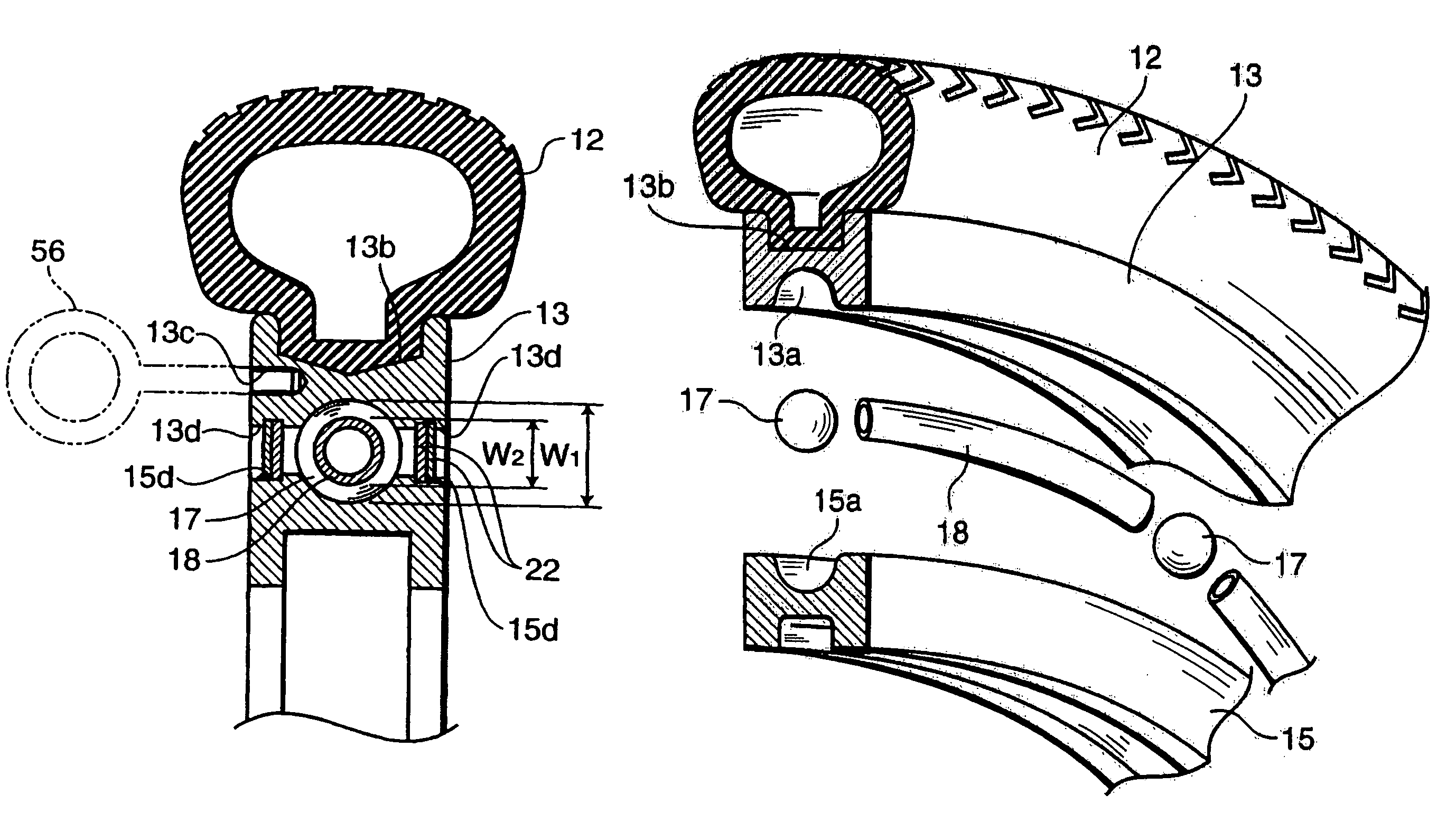
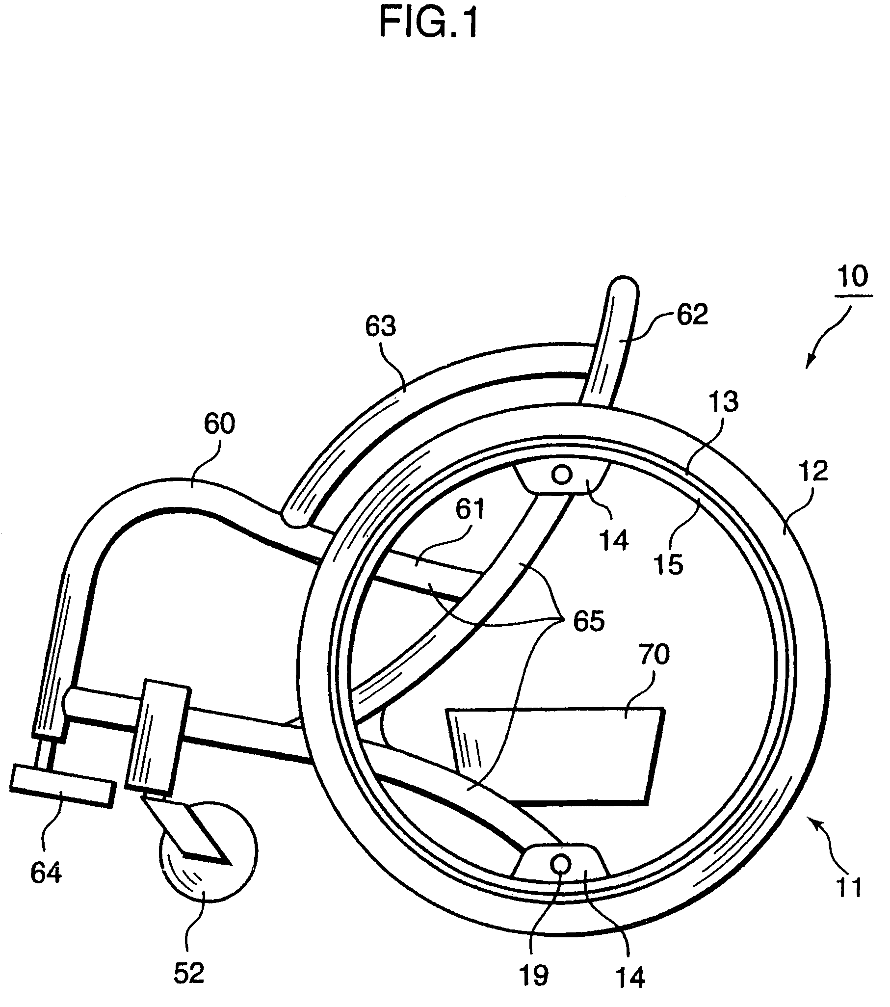
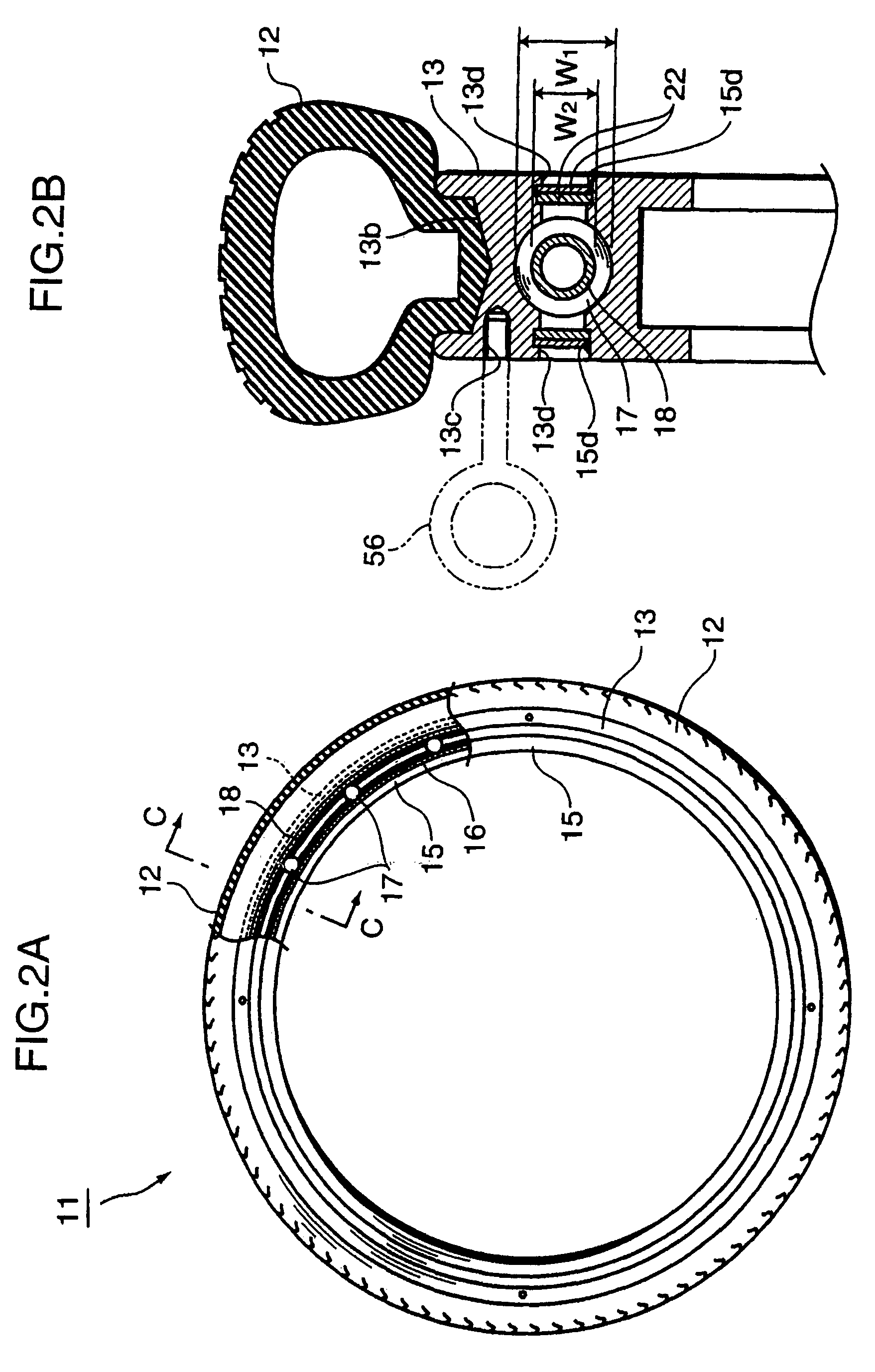
[0034]FIG. 1 is a side view showing a wheelchair 10 according to an embodiment 1 of the present invention. Hand rims 56 are omitted in Figure. Further, FIG. 2A is a partially broken side view showing a drive wheel 11 of the wheelchair 10, and FIG. 2B is a sectional enlarged view taken along the line C-C shown in FIG. 2A. FIG. 3 is a exploded perspective view of the drive wheel 11. The same components as those in FIG. 11 and FIG. 12 are denoted by the same reference numerals, and overlapping explanations are omitted.

[0035]The drive wheel 11 consists of a rubber tire 12, a metallic (e.g., aluminum) outer ring 13 mounted on the inner periphery of the tire 12, a metallic (e.g., aluminum) inner ring 15 which is concentric with the outer wheel 13 and positioned inside the outer ring 13, twelve balls (rolling elements) 17 interposed between the outer ring 13 and the inner ring 15, twelve retainers (spacers) 18 interposed between the balls 17, and a mounting member for a frame 14 mounted to...

embodiment 2

[0048]FIG. 6A is a side view showing a drive wheel (wheel for a wheelchair) 21 according to an embodiment 2 of the present invention, and FIG. 6B is a front view thereof.

[0049]The drive wheel 21 of the second embodiment 2 is one in which the mounting member for a frame 14 in the drive wheel 11 of the embodiment 1 is replaced with a mounting member for a hub 24, and the other configuration is the same as that of the drive wheel 11 of the embodiment 1.

[0050]The mounting member for a hub 24 has leg parts 24a, 24b and 24c extending in three directions from the rotational center (rotational centers of the inner wheel 15 and the outer ring 13) of the drive wheel 21, and spaces 26a, 26b and 26c are defined between the leg parts 24a, 24b and 24c, respectively. The top parts of the leg parts 24a, 24b and 24c are fixed by welding to the inner peripheral face of the inner ring 15. Further, to the rotational center of the drive wheel 21, a connecting member 25 extending toward the chair unit 60...

embodiment 3

[0054]FIG. 8 is a perspective view showing a wheelchair 30 according to an embodiment 3 of the present invention, which is a wheelchair for playing quad rugby.

[0055]A drive wheel of the wheelchair 30 of the embodiment 3 is the same as the drive wheel 11 used in the embodiment 1, provided that the drive wheel 30 is mounted to the frame 65 via the mounting member 14 for a frame at five points in the present embodiment 3, although the drive wheel 11 is mounted to the frame 65 at two points in the embodiment 1. Further, protective boards 35 are disposed so as to surround the chair unit 60, the drive wheel 11 and casters (not shown) of the wheelchair.

[0056]Quad rugby is a strenuous sport in which wheelchairs crash into each other. Therefore, since the chair unit 60 and the drive wheel 51 are connected via the hub 55 like the conventional example 1, a shock applied to the drive wheel 51 concentrates on the hub 55, whereby the wheel rotating axis of the hub 55 is deformed, as a result, def...


PUM


Abstract

A wheel for a wheelchair according to the present invention includes: an outer wheel or ring mounted on the inner periphery of a tire; an inner ring connected with a wheelchair frame (concentric with the outer ring and positioned inside the outer ring); a plurality of rolling elements interposed between the outer ring and the inner ring, arranged with an interval between each other in a circumferential direction; and a plurality of spacers (retainers or interval-holding members) for holding intervals between the rolling elements. Each spacer is in a shape extending along a circumferential direction of the outer ring and the inner ring, and is provided between the rolling elements respectively. The wheel does not have a hub and spokes, and the inner peripheral side does not rotate, and further the wheel weight is light. The wheelchair of the present invention includes the wheel for a wheelchair.

Description

TECHNICAL FIELD[0001]The present invention relates to wheelchairs, wheels for a wheelchair, and a method of manufacturing wheels for a wheelchair.BACKGROUND ART[0002]FIG. 11 is a perspective view showing a conventional self-traveling manual wheelchair 50. The wheelchair 50 has such a configuration that wheels are mounted to a chair unit 60. The wheels include large drive wheels 51 mounted on the transverse sides of the chair unit 60, and small casters 52 mounted on both front corners. The drive wheel 51 has such a configuration that a tire 53 is fixed to a hub 55 with spokes 54, and that a hand rim 56 for transmitting a driving force by a hand of a user is mounted to the drive wheel 51. The chair unit 60 consists of a seat surface 61, a back rest 62, arm rests 63, leg supports 64, and a frame65 for connecting them so as to form the chair unit. Further, on the rear side top parts of the frame 65, grips 65a used when a carrier pushes the wheelchair are mounted.[0003]The drive wheel 51...

Claims


Application Information

Patent Timeline
Patent Type & Authority Patents(United States)
IPC IPC(8): B60B9/10B60B9/18A61G5/00A61G5/02A61G5/10B60B33/00
CPCA61G5/00A61G5/02A61G5/028B60B21/02B60B3/001B60B3/04B60B3/048A61G5/10
Inventor MATSUDA, YASUSHIYASUI, TADASHIHOSHIDE, KAORUOGATA, TAKASHI
Owner THK CO LTD
Why Eureka
Try Eureka