Disinfection device for guiding air flow direction

A disinfection device and air technology, applied in the field of air purification, can solve the problems of incomplete purification of air and limited diffusion of disinfection gas, and achieve the effect of improving sterilization effect and ensuring sterility.

Pending Publication Date: 2022-02-15
大自然智能物联科技(北京)有限公司
View PDF5 Cites 0 Cited by
  • Summary
  • Abstract
  • Description
  • Claims
  • Application Information

AI Technical Summary

Problems solved by technology

[0003] The commonly used disinfection equipment is the disinfection machine. The disinfection machine is a machine made artificially for the purpose of removing or reducing toxic substances. way, resulting in a limited rang

Method used


Image

  • Disinfection device for guiding air flow direction
  • Disinfection device for guiding air flow direction
  • Disinfection device for guiding air flow direction

Examples


Embodiment 1

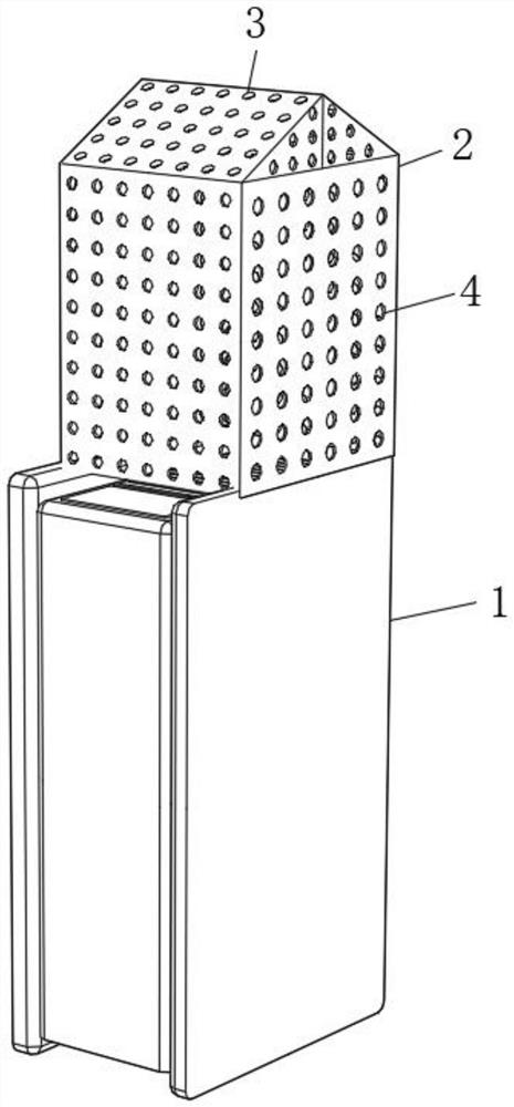
[0029] Such as figure 1 As shown, the present invention provides a technical solution: a disinfection device for guiding air flow, including a disinfection machine body 1, a lower diversion cover body 2 and an upper diversion cover body 3, and the lower diversion cover body 2 is installed on the disinfection machine The top of the sterilizer body 1 on both sides of the air outlet of the body 1, the lower diversion cover 2 is a hollow structure, the top of the lower diversion cover 2 is welded to the bottom of the upper diversion cover 3, the upper diversion cover 3 and The lower diversion cover body 2 is provided with a diversion hole 4, and the pitch of the diversion hole 4 is 1 cm. The top angle is 90°.

[0030] In this embodiment, the present invention is provided with an upper diversion cover body 3 and a lower diversion cover body 2. When the sterilizer body 1 is working, the lower diversion cover body 2 and the upper diversion cover body 3 are provided. , guide the air...

Embodiment 2

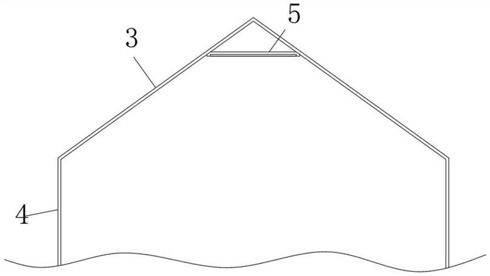
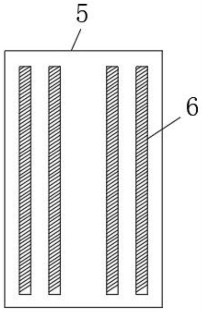
[0032] Such as Figure 2-4As shown, a lamp panel 5 is arranged between the inner top of the upper diversion cover body 3, and a disinfection gas catalytic lamp 6 is installed on the lamp panel 5. The model of the disinfection gas catalytic lamp 6 is ZW18D15Y-U217, and the lower diversion cover body 2 It consists of a substrate 21, an inner surface coating 22 and an outer surface coating 23, the substrate 21 is made of polytetrafluoroethylene, the inner surface coating 22 is arranged on the inner surface of the lower diversion cover body 2, and the inner surface coating 22 is made of Photocatalytic coating, the photocatalytic coating is made by adding nano-TiO2 to the ordinary coating, the outer surface coating 23 is arranged on the outer surface of the lower diversion cover body 2, and the outer surface coating 23 is made of high-grade silicone acrylic acid paint, The materials of the lower diversion cover 2 and the upper diversion cover 3 are identical, and the bottom cross-s...


PUM


Abstract

The invention provides a disinfection device for guiding the air flow direction, and relates to the technical field of air purification. The disinfection device comprises a disinfection machine body, a lower flow guide cover body and an upper flow guide cover body, wherein the lower flow guide cover body is installed at the top of the disinfection machine body on the two sides of an air outlet of the disinfection machine body, the lower flow guide cover body is of a hollow structure, the top of the lower flow guide cover body is welded with the bottom of the upper flow guide cover body, and the cross section of the bottom of the upper flow guide cover body is completely the same as that of the lower flow guide cover body.By arranging the upper flow guide cover body and the lower flow guide cover body, in the working process of the disinfection machine body, the lower flow guide cover body and the upper flow guide cover body are arranged, air is guided upwards to form an air flow which is matched with the breathing space of a human body, and air within the range of one meter to two meters away from the ground in the three-dimensional middle link forms drizzle to effectively guide disinfection factors to clean within the range of one meter to two meters away from the ground in the air.

Description

technical field [0001] The invention relates to the technical field of air purification, in particular to a disinfection device for guiding air flow. Background technique [0002] The indoor environment is contaminated by pathogens on suspended particles, such as bacteria and viruses; volatile gaseous pollutants after decoration, such as radon, formaldehyde, benzene series, ammonia, etc.; inhalable particles, such as dust, smoke, pollen, etc.; life Odor, such as human metabolism, musty smell, garbage smell, etc.; outdoor air pollution, such as industrial waste gas, vehicle exhaust, soil dust, etc.; the above can also be collectively referred to as air pollution, and the way to reduce or eliminate this kind of air pollution is air disinfect. [0003] The commonly used disinfection equipment is the disinfection machine. The disinfection machine is a machine made artificially for the purpose of removing or reducing toxic substances. The method leads to a limited diffusion ran...

Claims


Application Information

Patent Timeline
IPC IPC(8): F24F8/24F24F8/30F24F8/10F24F8/22F24F13/08
CPCF24F8/24F24F8/30F24F8/10F24F8/22F24F13/08Y02A50/20
Inventor 吴新春刘声
Owner 大自然智能物联科技(北京)有限公司
Why Eureka
Try Eureka