Compact diversity antenna

a technology of antennas and antenna supports, applied in the direction of antennas, antenna supports/mountings, radiating element structural forms, etc., can solve the problems of increasing the complexity and variety of advanced functions and services that the terminals are capable of performing, and adding to the volume and weight of the terminal

Inactive Publication Date: 2008-07-29
YING ZHINONG
View PDF12 Cites 33 Cited by
  • Summary
  • Abstract
  • Description
  • Claims
  • Application Information

AI Technical Summary

Problems solved by technology

The development in electronics has not only made it possible to miniaturise the components of the terminals, the complexity and variety of advanced functions and services which the terminals are capable of performing is also ever increasing.
Still, this means a side length of about 20 to 25 mm which, in applications involving use of a small communications device such as a portable receiving terminal, adds to much volume and weight to the terminal.

Method used


Image

  • Compact diversity antenna
  • Compact diversity antenna
  • Compact diversity antenna

Examples


first embodiment

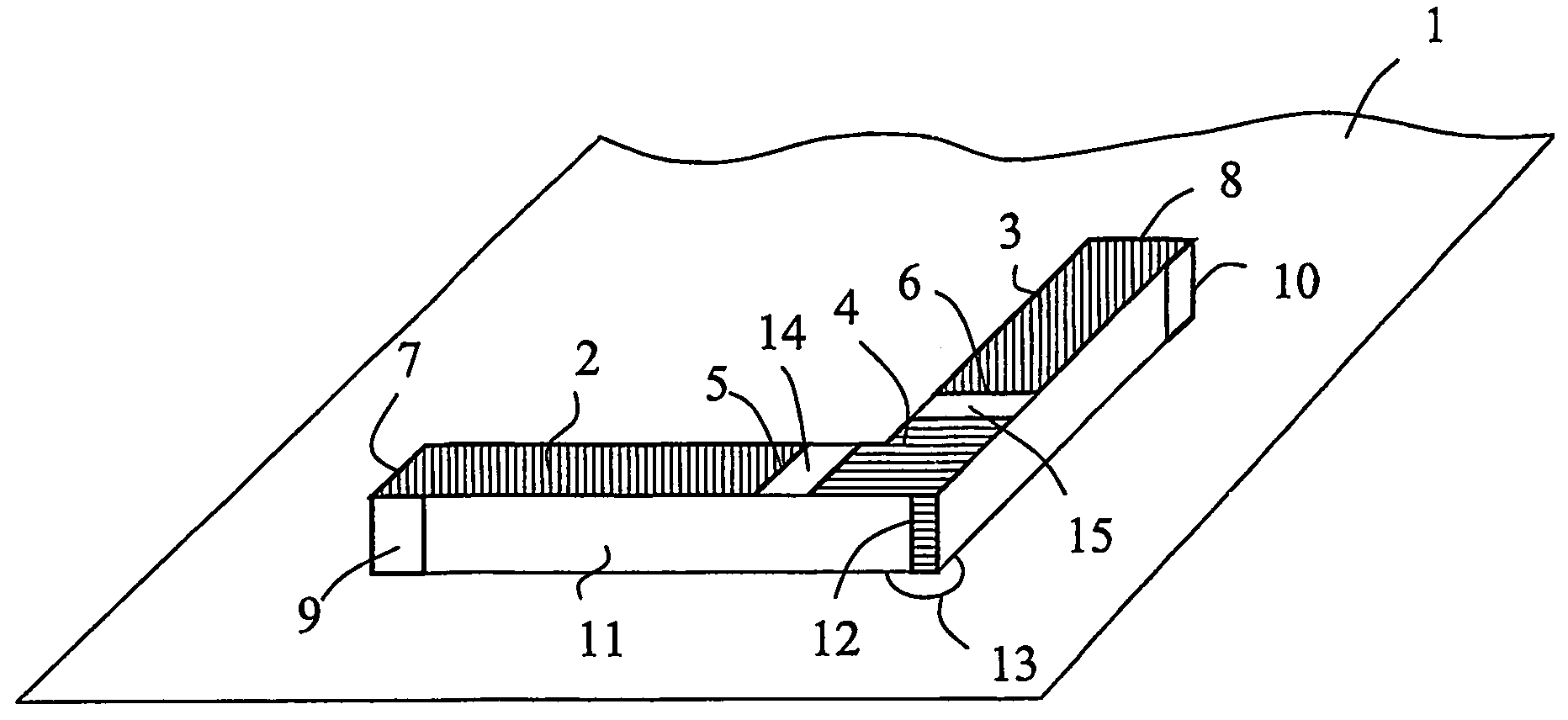
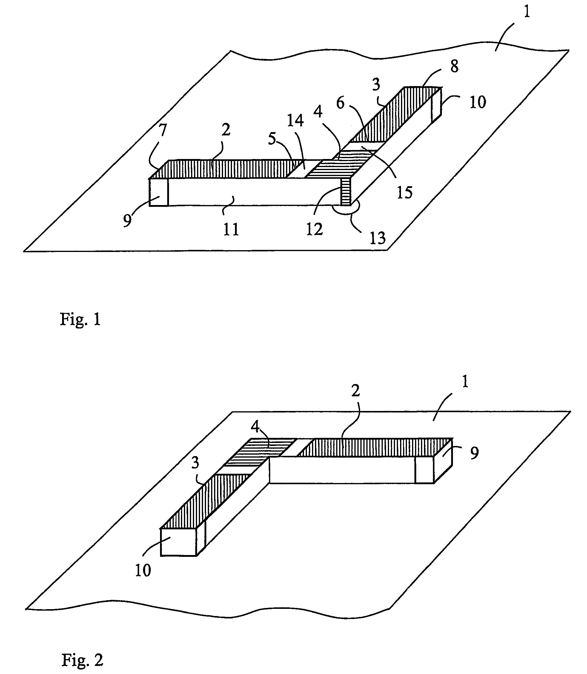
[0032]FIG. 1 schematically illustrates a compact diversity radio antenna according to the present invention, and FIG. 2 illustrates the same embodiment as seen from an opposite angle. The antenna is carried on a support structure, such as a printed circuit board, PCB, preferably defining a substantially plane support surface. The support structure includes an electrical ground substrate 1, which may cover a major portion of the support structure. Alternatively, the ground substrate 1 may be confined to a portion of the support structure, over which portion the antenna is placed. The ground substrate 1 is preferably realised as a material layer on an outer side or an intermediate layer of a PCB. In another embodiment, the ground substrate may be formed directly on a bottom side of the antenna. In FIG. 1, the ground substrate 1 is illustrated as a flat substrate extending beyond the antenna.

[0033]The antenna is placed on or adjacent to the ground substrate 1, and comprises 10 a substa...

second embodiment

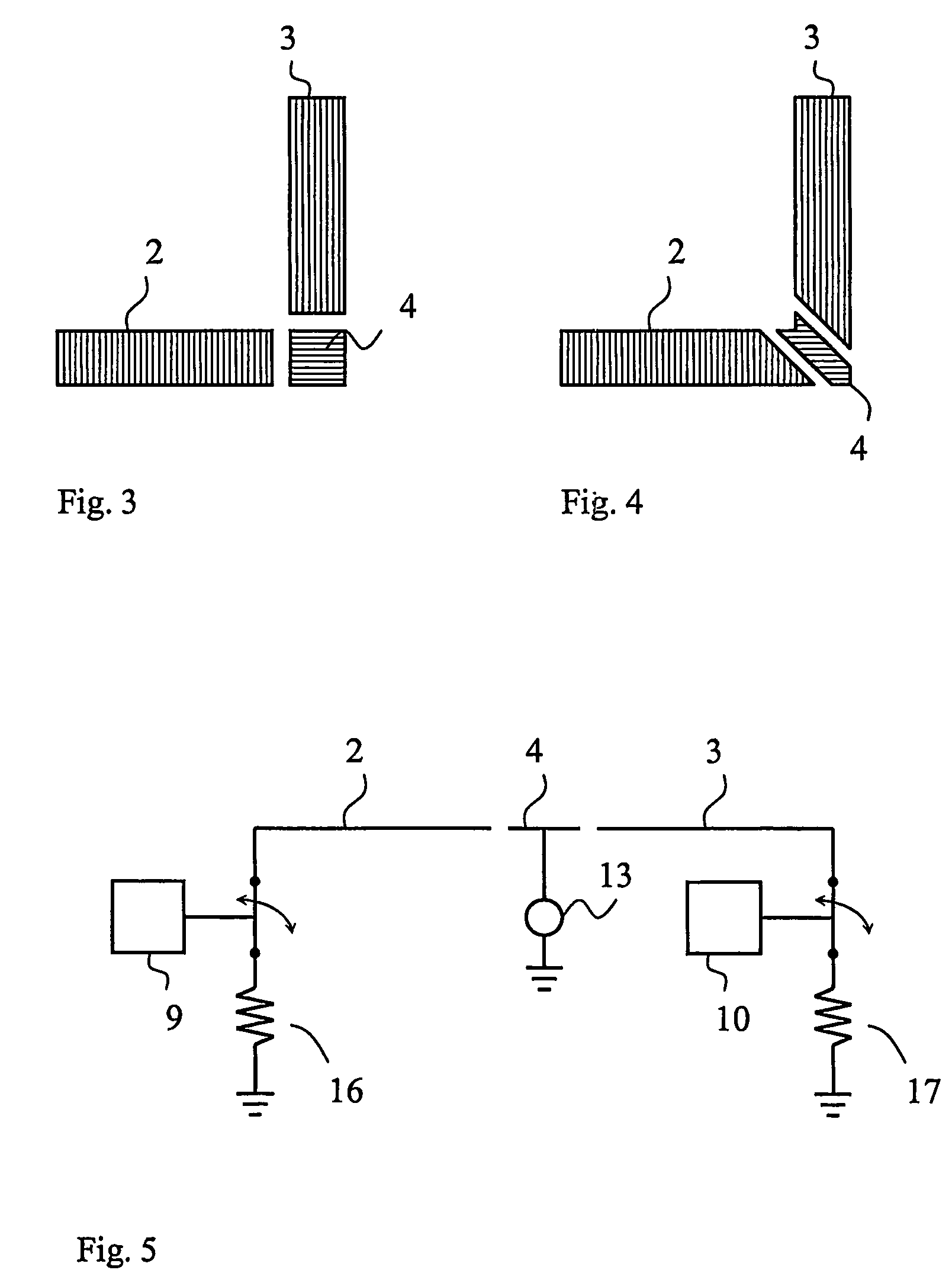
[0036]FIG. 3 illustrates a second embodiment, only showing the antenna elements 2,3 and excitation electrode 4. In this example, excitation electrode 4 is rectangular, or even quadratic, and therefore does not extend into the legs of the first surface of dielectric member 11.

[0037]FIG. 4 illustrates a third exemplary embodiment, in which excitation electrode 4 extends substantially diagonally over the intersection of the legs of the dielectric member 11. Also the first ends 5 and, respectively, of the antenna elements 2,3 are angled such that the gaps 14,15 have constant widths. Other specific embodiments of the pattern of the antenna structure are of course possible, and the antenna elements may e.g. be meandered in their extension between the respective first ends 5,6 and second ends 7,8.

[0038]The antenna elements 2,3 are selectively connected to ground substrate 1, by means of ground connector switch means 9,10. The ground connector switch means 9,10 are preferably devised to con...


PUM


Abstract

A diversity radio antenna includes a ground substrate and two elongated antenna elements. The antenna elements each extend between respective opposing ends thereof in a plane parallel to and spaced from the ground substrate. An excitation electrode is interposed between the respective ends. A ground connector switch is configured to selectively connect and disconnect the ground substrate to the antenna elements for controlling radiation beam pattern and polarisation diversity of the antenna. The ground connector switch is configured to selectively connect the antenna elements to the ground substrate for adapting the antenna to a circularly-polarised radio wave, or to disconnect one of the antenna elements from the ground substrate for adapting the antenna to a linearly-polarised radio wave.

Description

RELATED APPLICATIONS[0001]The present application is a 35 U.S.C. §371 national phase application of PCT International Application No. PCT / EP2004 / 001503, having an international filing date of Feb. 18, 2004 and claiming priority to European Patent Application No. 03075785.0, filed Mar. 18, 2003 and U.S. Provisional Application No. 60 / 458,170 filed Mar. 27, 2003, the disclosures of which are incorporated herein by reference in their entireties. The above PCT International Application was published in the English language and has International Publication No. WO 2004 / 084344.FIELD OF THE INVENTION[0002]The present invention relates generally to antennas for radio communication terminals and, in particular, to compact antennas devised to be incorporated into portable terminals, and which are capable of transmission and reception diversity.BACKGROUND[0003]Since the end of the 20th century the cellular telephone industry has had enormous development in the world. From the initial analog sy...

Claims


Application Information

Patent Timeline
Patent Type & Authority Patents(United States)
IPC IPC(8): H01Q1/38H01Q1/24H01Q3/24H01Q9/04H01Q21/24
CPCH01Q1/243H01Q1/38H01Q9/0421H01Q21/245H01Q9/0442H01Q21/24H01Q9/0428
Inventor YING, ZHINONG
Owner YING ZHINONG
Why Eureka
Try Eureka