Optical waveform measuring apparatus and optical waveform measuring method

a technology of optical waveform and measuring apparatus, which is applied in the direction of multiplex communication, transmission monitoring, instruments, etc., can solve the problems of insufficient operation bandwidth of electronic circuit, insufficient measurement of signal light waveform in arbitrary polarization state, and long time consumption, so as to remove the dependency of the generation of intensity correlation signal light, the effect of simple control

Inactive Publication Date: 2006-07-20
FUJITSU LTD
View PDF9 Cites 32 Cited by
  • Summary
  • Abstract
  • Description
  • Claims
  • Application Information

AI Technical Summary

Benefits of technology

[0040] As described above, according to the present invention, the polarization state control unit can control the polarization state of a light under measurement to be inputted to the sampling result outputting unit to carry out the waveform measurement through the use of a light outputted from the sampling result outputting unit, which provides an advantage of removing the dependency of the generation of an intensity correlation signal light upo

Problems solved by technology

Usually, an operating bandwidth limitation of an electronic circuit, considered to be 50 GHz, is not always sufficient to the fine observation of a signal of 40 Gb/s.
However, since the intensity correlation signal light developing within the aforesaid crystals depends upon the polarization states of the incident light under measurement and the sampling light pulse, difficulty is experienced in measuring a signal light waveform in an arbitrary polarization state.
In addition, in a case in which each of the polarization states of the light under measurement and the sampling light pulse is set in a manual fashion, it needs long time to set the optimum polarization states of the light under measurement and the sampling light.
And not only that, in the case of the manual setting, difficulty is encountered in securing the accuracy and reproducibility.
In particular, in a case in which a plurality of lights under mea

Method used


Image

  • Optical waveform measuring apparatus and optical waveform measuring method
  • Optical waveform measuring apparatus and optical waveform measuring method
  • Optical waveform measuring apparatus and optical waveform measuring method

Examples


first embodiment

[A] Description of First Embodiment

[0063] [A-1] Configuration

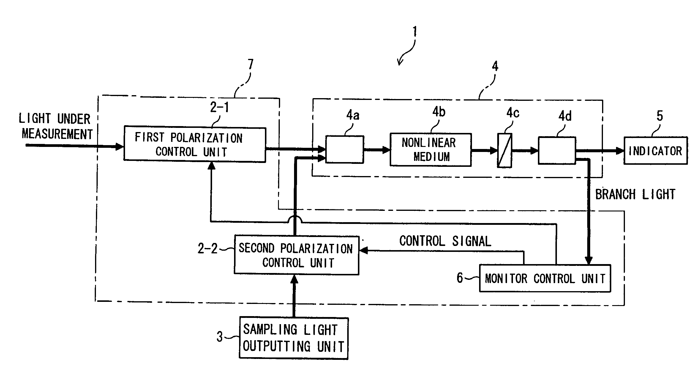
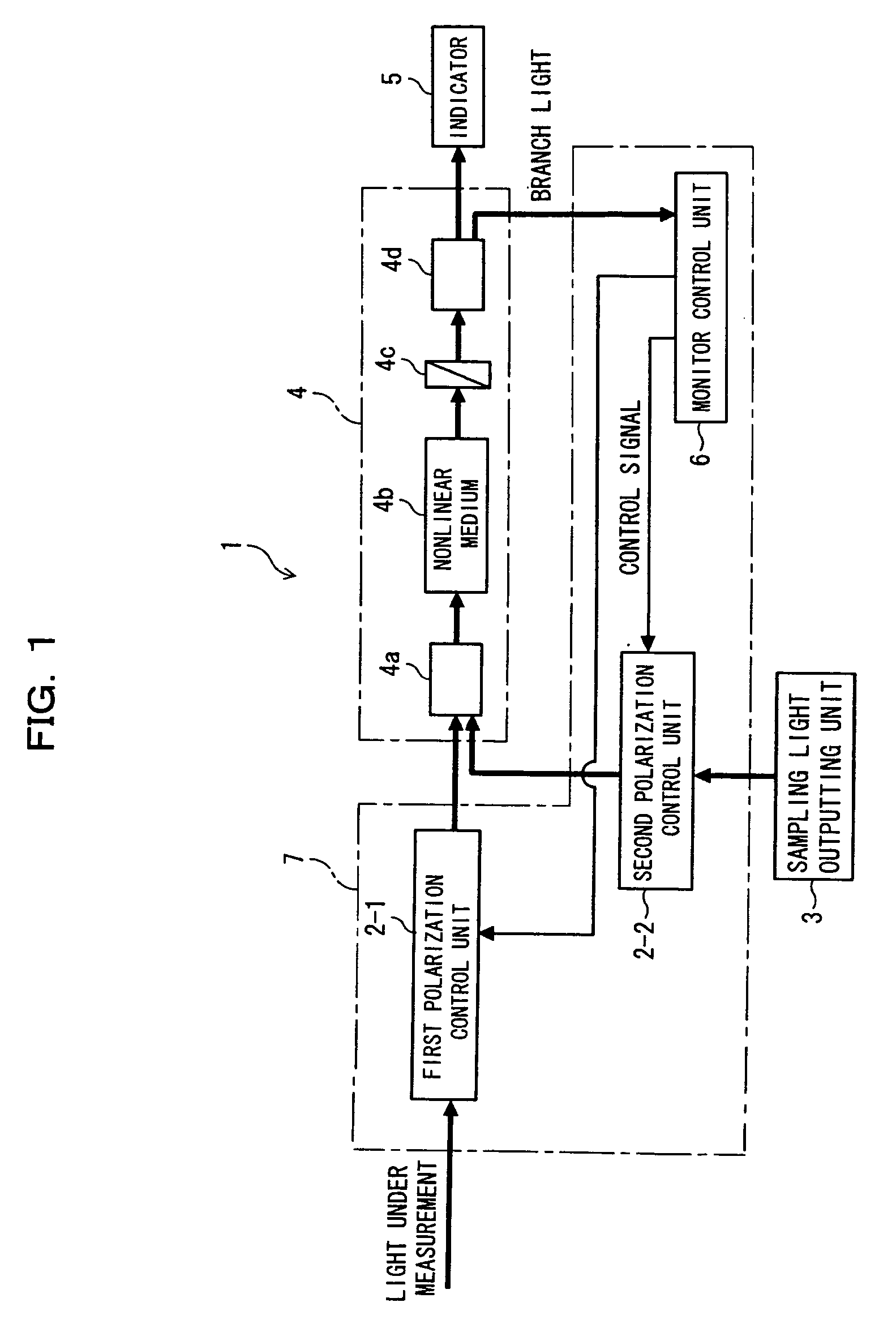
[0064]FIG. 1 is a block diagram showing an optical waveform measuring apparatus according to a first embodiment of the present invention. The optical wave form measuring apparatus 1 shown in FIG. 1 is for measuring a waveform of light under measurement (light to be measured) and, concretely, has a function to display a waveform by means of sampling. In this case, the optical waveform measuring apparatus 1 is made up of a first polarization control unit 2-1, a second polarization control unit 2-2, a sampling light outputting unit 3, a sampling result outputting unit 4, a wave form indicator 5 and a monitor control unit 6.

[0065] In this configuration, the sampling light outputting unit 3 is made to output a sampling light pulse for sampling the aforesaid light under measurement, and a sampling light to be outputted from the sampling light outputting unit 3 has a pulse width narrower than the light under measurement and fur...

second embodiment

[B] Description of Second Embodiment

[0099] [B-1] Construction

[0100]FIG. 3 is a block diagram showing an optical waveform measuring apparatus 11 according to a second embodiment of the present invention. The optical waveform measuring apparatus 11 shown in FIG. 3 is designed to further develop each component of the above-described optical waveform measuring apparatus 1 according to the first embodiment. That is, the optical waveform measuring apparatus 11 according to the second embodiment is also made up of a first polarization control unit 12-1, a second polarization control unit 12-2, a sampling light outputting unit 13, a sampling result outputting unit 14, an indicator 15 and a monitor control unit 16.

[0101] In this configuration, the sampling light outputting unit 13 is for supplying a sampling light pulse through the first polarization control unit 12-1 to the sampling result outputting unit 14 and, as shown in FIG. 3, it is composed of a frequency generating unit 18 and a s...

third embodiment

[C] Description of Third Embodiment

[0181]FIG. 15 is an illustration of an optical waveform measuring apparatus 31 according to a third embodiment of the present invention. The optical waveform measuring apparatus 31 shown in FIG. 15 differs from the above-described second embodiment in the mode of setting control on the first and second polarization control units 12-1 and 12-2 by a monitor control unit 16′ prior to the waveform measurement, and other configuration is basically the same and, in FIG. 15, the same reference numerals as those in FIG. 3 basically designate the same parts.

[0182] The monitor control unit 16′ of the optical waveform measuring apparatus according to the third embodiment is composed of a power meter 16a′ and a comparison controller 16b′ which are different in function from those (reference numerals 16a and 16b) in the second embodiment, and the setting control on the aforesaid first and second polarization control units 12-1 and 12-2 is facilitated in compar...


PUM


Abstract

The present invention relates an optical waveform measuring apparatus designed to eliminate the polarization dependency of an intensity correlation signal without a polarization diversity arrangement. The apparatus comprises a sampling light outputting unit for outputting a sampling light pulse to sample light under measurement, a sampling result outputting unit for developing a nonlinear optical effect stemming from the light under measurement and the sampling light pulse from the sampling light outputting unit to output light corresponding to a result of the sampling of the light under measurement, and a polarization state control unit for, before the start of the measurement of the light under measurement, carrying out control on the basis of a power level of the light from the sampling result outputting unit so that a polarization state of the light under measurement, which is to be inputted to the sampling light output unit, is placed into a predetermined state.

Description

BACKGROUND OF THE INVENTION [0001] 1) Field of the Invention [0002] The present invention relates to an optical waveform measuring apparatus and an optical waveform measuring method, and more particularly to optical waveform measuring apparatus and method suitable for use in observing an optical pulse waveform, so as to make a faithful observation of an actual waveform. The optical pulse waveform encounters difficulty of accurate observations in fine detail through the use of electronic measurements, due to operating speed limitations on electronic circuits. [0003] 2) Description of the Related Art [0004] In optical communications, the observation of an optical pulse waveform is a function needed for the evaluation of quality of an optical signal at receiver ends, and it is also applicable to a signal repeater or a node of an optical network for monitoring quality of signal. In addition, it exhibits a function indispensable to the evaluation of optical parts. Along with an increase ...

Claims


Application Information

Patent Timeline
IPC IPC(8): H04B10/00G01J11/00
CPCG01J11/00
Inventor FUTAMI, FUMIOWATANABE, SHIGEKI
Owner FUJITSU LTD
Why Eureka
Try Eureka