Polarization diversity receiver for optical transmission system

a technology of optical transmission system and polarization diversity, applied in electromagnetic transmission, electrical equipment, transmission, etc., can solve problems such as substantial noise penalty in input states, and achieve the effects of reducing the number of electrical signals, reducing size and cost, and relatively simple optical sections

Active Publication Date: 2007-04-24
CIENA
View PDF5 Cites 33 Cited by
  • Summary
  • Abstract
  • Description
  • Claims
  • Application Information

AI Technical Summary

Benefits of technology

[0014]By having the transformations to points not on mutually perpendicular axes and spaced apart, the number of polarization component optical signals or component electrical signals can be reduced from the six used in the above mentioned prior art, yet still retaining most of the advantages of polarization diversity. By reducing the number of such signals, the number of optical components can be reduced, the number of detectors can be reduced, and the complexity of the electronic processor can be reduced. This can enable significant cost and size reductions. The need for precise polarization tracking in the receiver can be reduced or eliminated completely. As coherent detectors need either polarization tracking or two detectors for in phase and quadrature components on each polarization component, the advantages appear more notable for the case of direct detectors.
[0071]Another aspect provides a method of offering a data transmission service over a transmission system using the receiver. The advantages of the invention can enable improvements to be made in the system performance such as being more reliable or more flexible, having a greater capacity, or being more cost effective. Consequently data transmission services can be enhanced, and the value of such services can increase. Such increased value over the life of the system, could prove far greater than the sales value of the equipment.

Problems solved by technology

If the detectors' polarization states do not have this maximal separation, there will be input states with a substantial noise penalty, even in the absence of PMD.

Method used


Image

  • Polarization diversity receiver for optical transmission system
  • Polarization diversity receiver for optical transmission system
  • Polarization diversity receiver for optical transmission system

Examples


Embodiment Construction

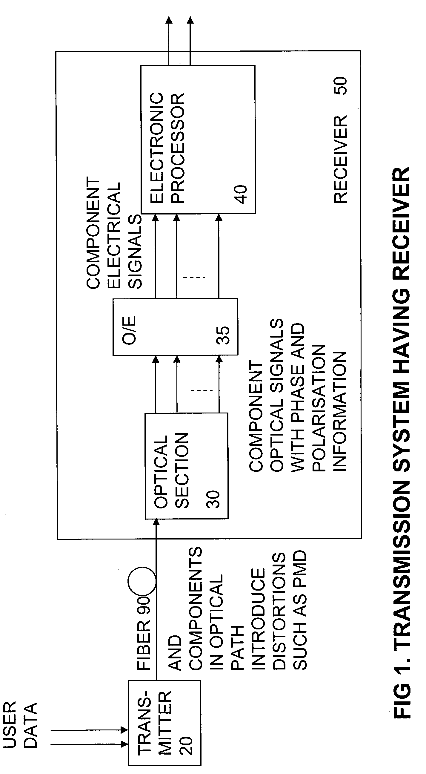
FIG. 1, Transmission System

[0087]FIG. 1 shows an example of an optical transmission system according to an embodiment of the invention. It includes a transmitter 20 coupled to a transmission fiber 90. User data is transmitted by the transmitter along the fiber following conventional principles. In typical systems the fiber may be many kilometres in length. The fiber and components in the optical path such as optical amplifiers and compensators, can introduce noise and distortions such as PMD. The receiver 50 tries to pick out the original signal from the noise.

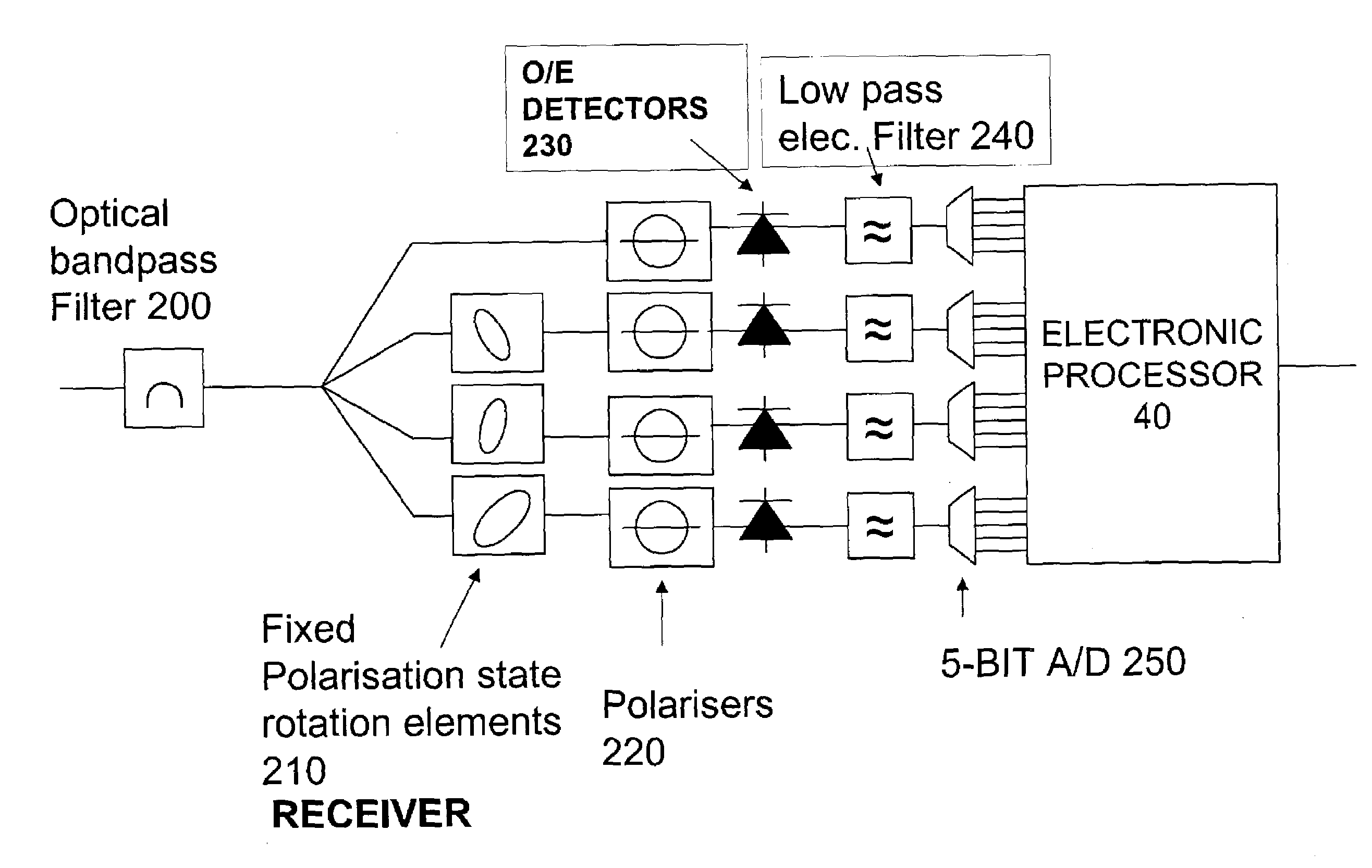
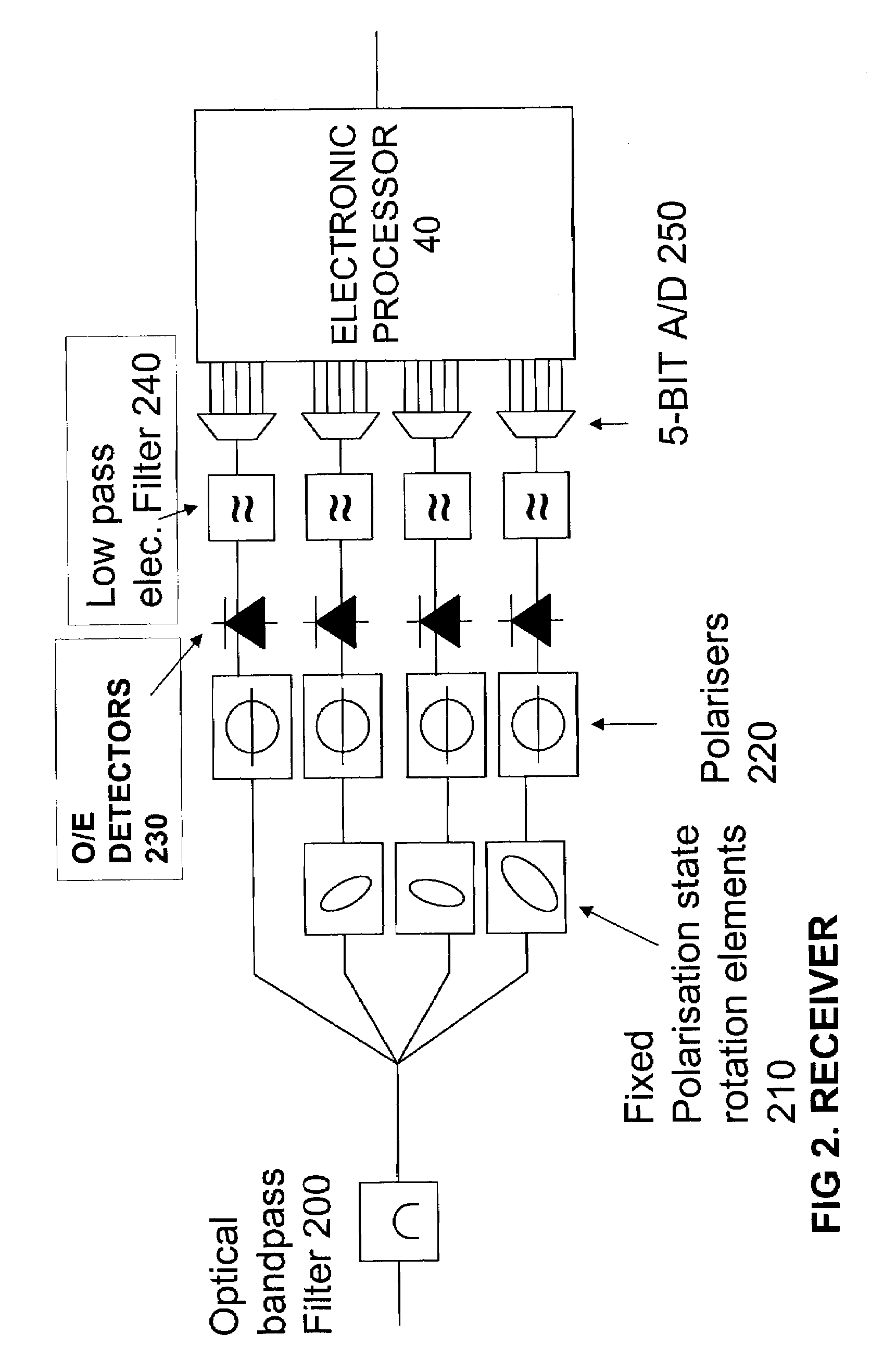
[0088]The receiver includes an optical section 30 which outputs component optical signals which include substantially all of the phase and polarisation information of the received optical signal. The component optical signals are converted into corresponding component electrical signals by optical to electrical converter 35 typically in the form of conventional direct detection square law detectors. The component electrical si...


PUM


Abstract

A polarization diversity receiver has an optical section for converting the received optical signal into four or five polarization diverse component optical signals that substantially represent amplitude and polarization state information of the received optical signal, by respective polarization transformations to respective points on a Poincaré sphere, the points being equally spaced apart to maximize polarization diversity, even in the worst case input polarization state. Detectors produce component electrical signals from each of the component optical signals, for electronic processing to compensate for PMD. By reducing the number of component optical signals significant cost and size reductions are enabled. The need for precise polarization tracking in the receiver can be reduced or eliminated completely. Balanced detectors can be used to reduce the number of electrical signals. The electrical processing can use sequence detection.

Description

FIELD OF THE INVENTION[0001]This invention relates to receivers for optical transmission systems, to nodes for such systems, to methods of receiving optical signals, and to methods of offering a transmission service over such apparatus.BACKGROUND TO THE INVENTION[0002]Known optical transmission systems can be broadly categorized as direct detection, or coherent detection systems. In direct detection systems, at the receiver, the signal power is measured and therefore any phase and polarization information in the optical signal is ignored and lost. In coherent detection systems, inphase and quadrature components of the optical field are detected, which enables the use of phase modulation as well as amplitude modulation, and so two channels can be transmitted having orthogonal phases. It is also known that two further channels can be transmitted using orthogonal polarizations, if in addition the receiver is polarization diverse. Direct detection systems have nevertheless dominated the...

Claims


Application Information

Patent Timeline
Patent Type & Authority Patents(United States)
IPC IPC(8): H04B10/06H04B10/158H04B10/18
CPCH04B10/2569H04B10/67H04B10/69
Inventor FLUDGER, CHRISTOPHEREPWORTH, RICHARDROBINSON, ALAN
Owner CIENA
Why Eureka
Try Eureka