Multi-beam, polarization diversity narrow-band cognitive antenna

a cognitive antenna, multi-beam technology, applied in diversity/multi-antenna system, polarisation/directional diversity, transmission, etc., to achieve the effect of increasing the antenna size, preserving power efficiency, and improving performan

Inactive Publication Date: 2011-07-21
DELPHI TECH INC +1
View PDF13 Cites 34 Cited by
  • Summary
  • Abstract
  • Description
  • Claims
  • Application Information

AI Technical Summary

Benefits of technology

[0016]The present invention is unique in that it addresses a method of achieving an adaptive high-gain, multi-beam antenna over a relatively narrow frequency band using principles of cognitive antennas, provides methods of maintenance of power efficiency, and describes a systematic method of improving performance by increasing antenna size.
[0017]The present invention provides a simple solution of forming a narrow beam cognitive antenna that preserves its power efficiency and operates over a narrow frequency band. This is accomplished by employing a plurality of resonant and / or sub-resonant antenna elements as well as lumped and distributed inductors and capacitors (realized via discrete components or as part of the antenna structure) that, through selective connection and disconnection actions, can form highly efficient narrow beam antennas. The present invention also provides a systematic approach to increasing the gain and the number of possible beams (or patterns) by varying the size and component count of the antenna while maintaining the narrow frequency band of operation.

Problems solved by technology

Prior SSA's also typically describe wide-band operation and do not address narrow-band features.

Method used


Image

  • Multi-beam, polarization diversity narrow-band cognitive antenna
  • Multi-beam, polarization diversity narrow-band cognitive antenna
  • Multi-beam, polarization diversity narrow-band cognitive antenna

Examples


Embodiment Construction

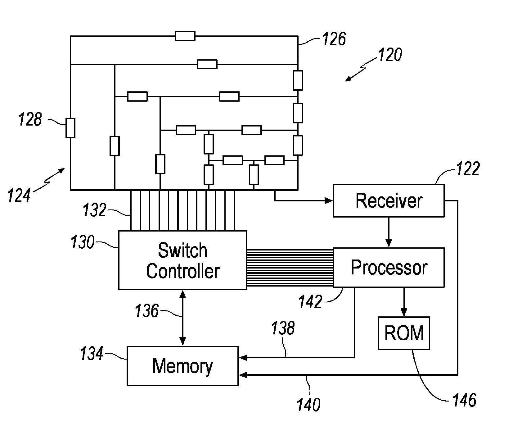
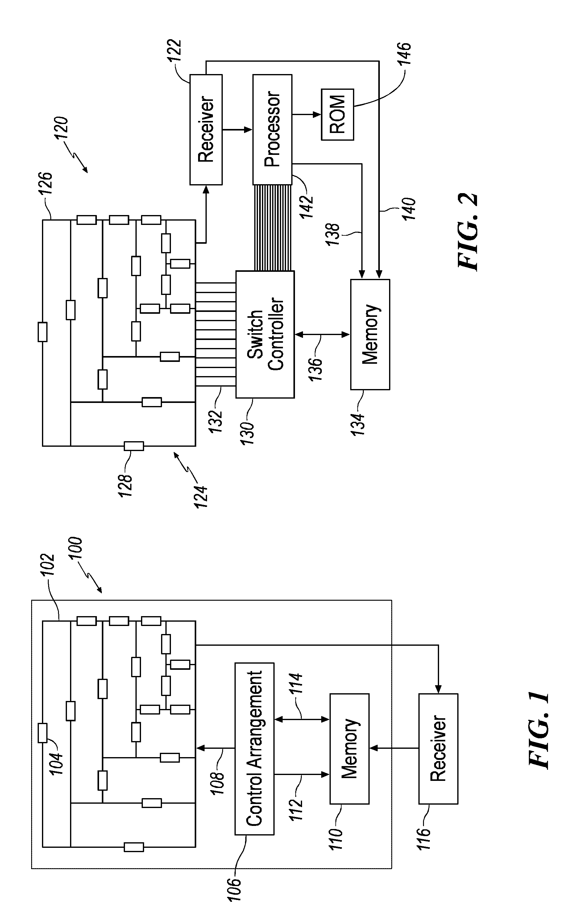
[0054]Technological advances in radio-frequency (RF) front-ends, such as reconfigurable antenna arrays, afford a new “hardware” dimension for dynamic spectrum access in cognitive wireless networks.

[0055]A smart antenna system is able to provide, if compared with existing technologies, higher system capacity, improved quality of service, suppress interferences, improved power consumption and higher frequency reuse. From a practical point of view, a smart antenna system combines an antenna array with digital signal processing techniques (adaptive beamforming techniques, direction of arrival procedures, etc.) in order to obtain a software steerable antenna pattern and direct the radiated power in (or receive from) the desired direction only.

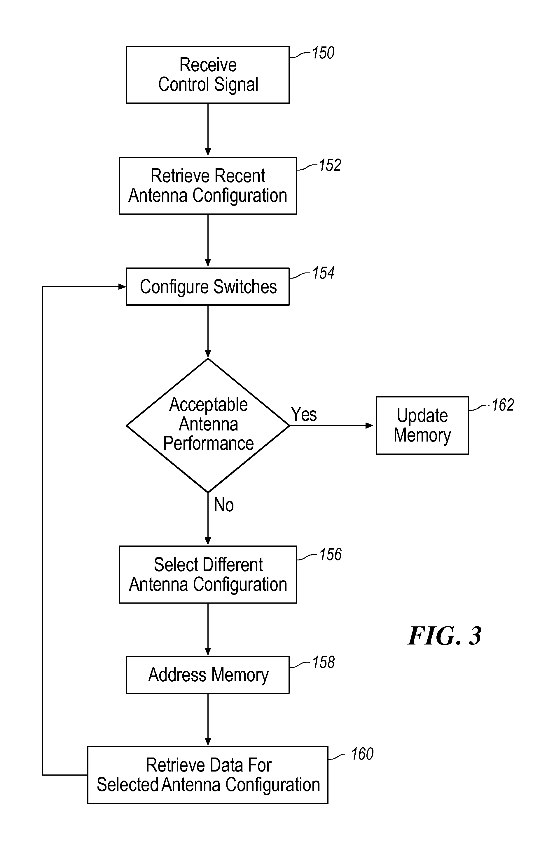
[0056]A cognitive antenna is substantially an antenna array able to provide a spatial-temporal scanning of the radio environment, and it is able to reconfigure itself in order to perform optimized communication capabilities.

[0057]Referring to FIG. 1...


PUM


Abstract

A multi-beam, polarization diversity, narrow-band cognitive antenna system is disclosed. The antenna system includes a plurality of antenna elements, switching elements, and transmission feed lines disposed on a PCB substrate, inside or on the enclosure of a consumer wireless device, on the airframe of an air vehicle, or on the surface of a ground vehicle. The plurality of switching elements are arranged with the antenna elements and transmission feed lines to, when selectively closed, electrically couple selected ones of the antenna elements and transmission feed lines to one another to generate an antenna configuration selected from a plurality of antenna configurations. A non-volatile memory is configured to store data representing at least some of the plurality of antenna configurations. A control arrangement operatively coupled to the plurality of switching elements and configured to close selected ones of the switching elements as a function of the data stored in said memory. Means are provided to selectively update the data on a function of previously selected antenna configurations.

Description

FIELD OF THE INVENTION[0001]This disclosure relates generally to wireless communication systems. More particularly, this disclosure relates to smart antennas including self-structuring antenna subsystems and self-structuring feeds operating in different beam modes.BACKGROUND OF THE INVENTION[0002]The vast majority of vehicles currently in use incorporate vehicle communication systems for receiving or transmitting signals. For example, vehicle audio systems provide information and entertainment to many motorists daily. These audio systems typically include an AM / FM radio receiver that receives radio frequency (RF) signals. These RF signals are then processed and rendered as audio output. A vehicle communication system may incorporate other functions, including, but not limited to, wireless data and voice communications, global positioning system (GPS) functionality, and satellite-based digital audio radio services (SDARS). The vehicle communication system may also incorporate remote ...

Claims


Application Information

Patent Timeline
Patent Type & Authority Applications(United States)
IPC IPC(8): H01Q3/24
CPCH01Q1/00H01Q3/01H04B7/10H01Q21/245H04B7/0874H01Q9/145
Inventor OZDEMIR, TAYFUNPAWLAK, ANDRZEJ M.
Owner DELPHI TECH INC
Why Eureka
Try Eureka