Lens module

a technology of lens module and lens body, which is applied in the direction of dynamo-electric components, dynamo-electric machines, instruments, etc., can solve the problems of large size, high manufacturing cost, and high power consumption of lens module, and achieve the effect of reducing cost and small siz

Inactive Publication Date: 2008-07-29
YOUNG OPTICS
View PDF9 Cites 8 Cited by
  • Summary
  • Abstract
  • Description
  • Claims
  • Application Information

AI Technical Summary

Benefits of technology

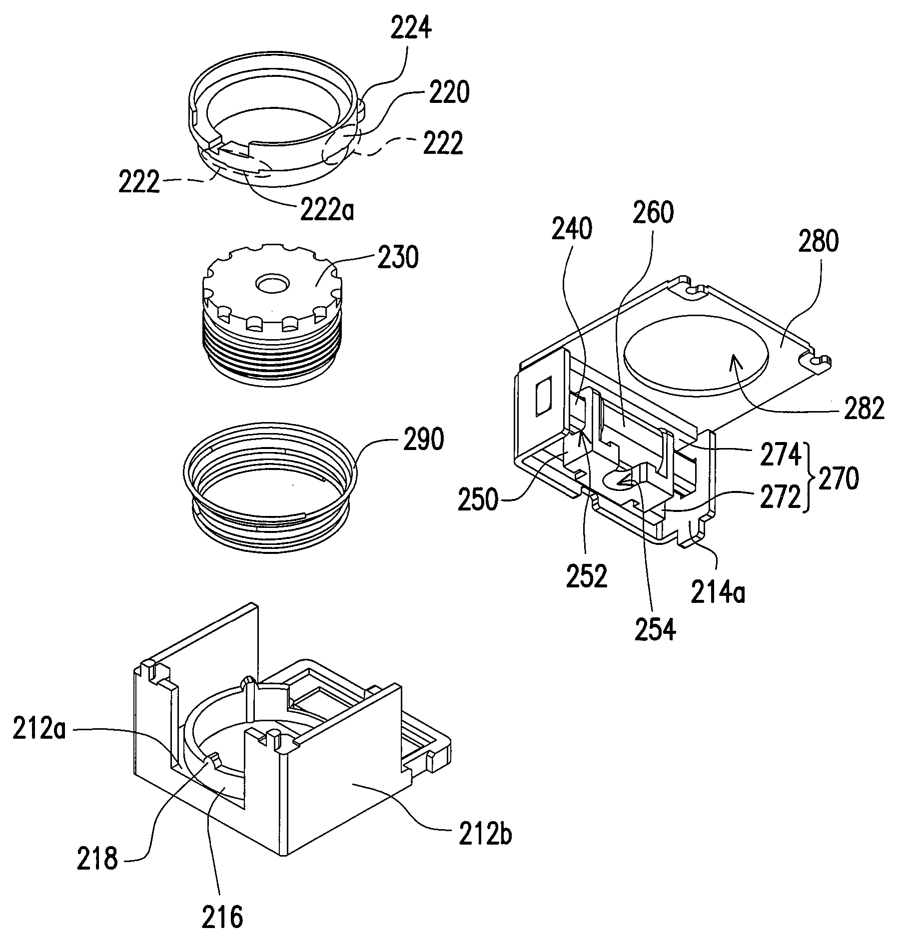
[0010]Accordingly, the present invention is directed to provide a lens module having multi-stage focusing function and of lower cost and smaller size.
[0013]According to the present invention, the sleeve is rotated by the moving of the coil supporter, so as to change the step in contact with the bumps of the annular carrier, and furthermore, to accomplish the purpose of focus adjustment. Since the structure of the lens module in the present invention is very simple, the material cost and the assembly cost of the device is reduced, and the size of the device is smaller. Moreover, no current has to be provided to the coil after focusing, so that the power consumption of the device can be reduced.

Problems solved by technology

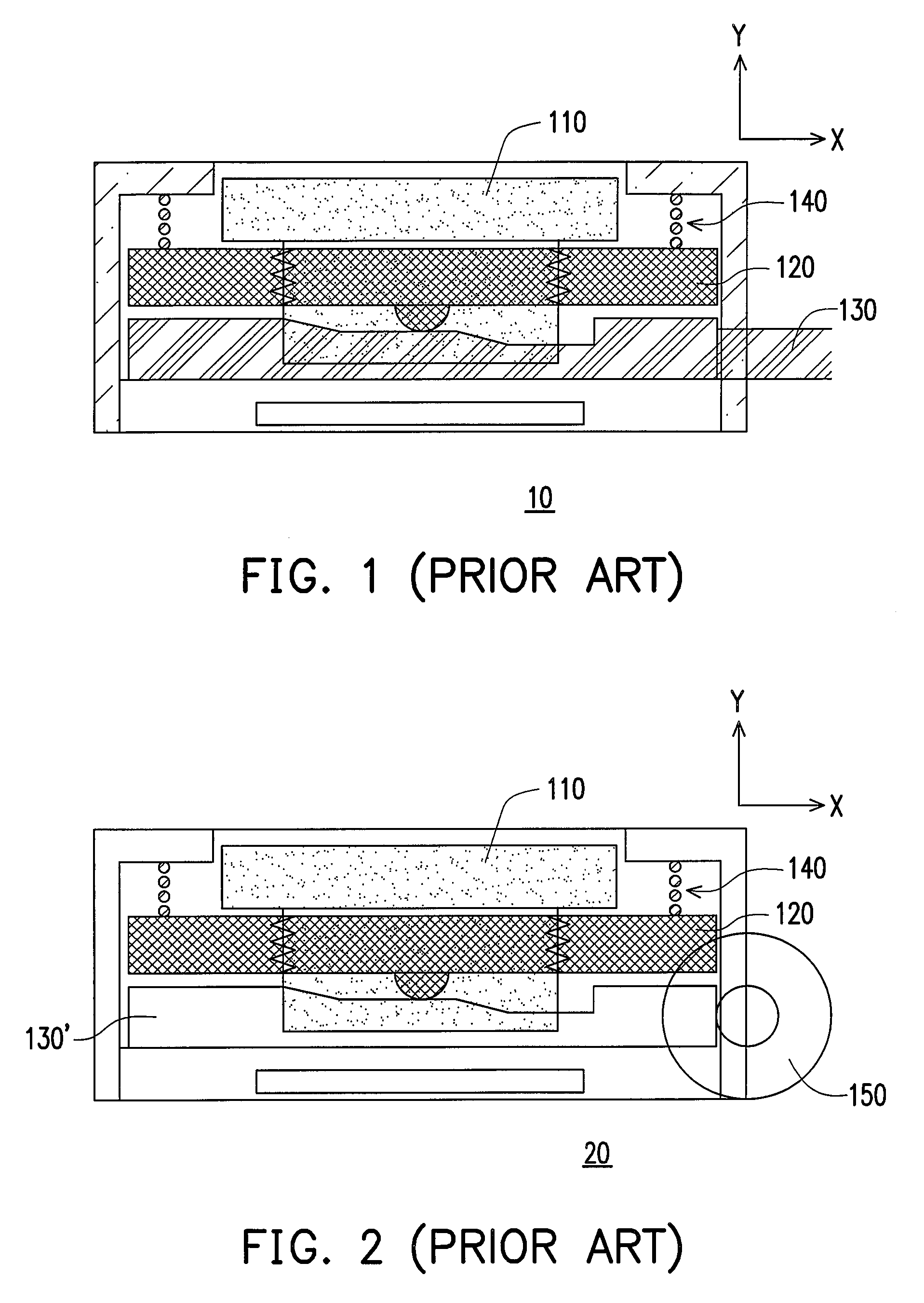
However, the lens module 10 is not convenient to use because it focuses manually.
Even though the lens module 20 focus automatically, the lens module 20 has large size and high manufacturing cost, and the power consumption thereof for focusing is high.
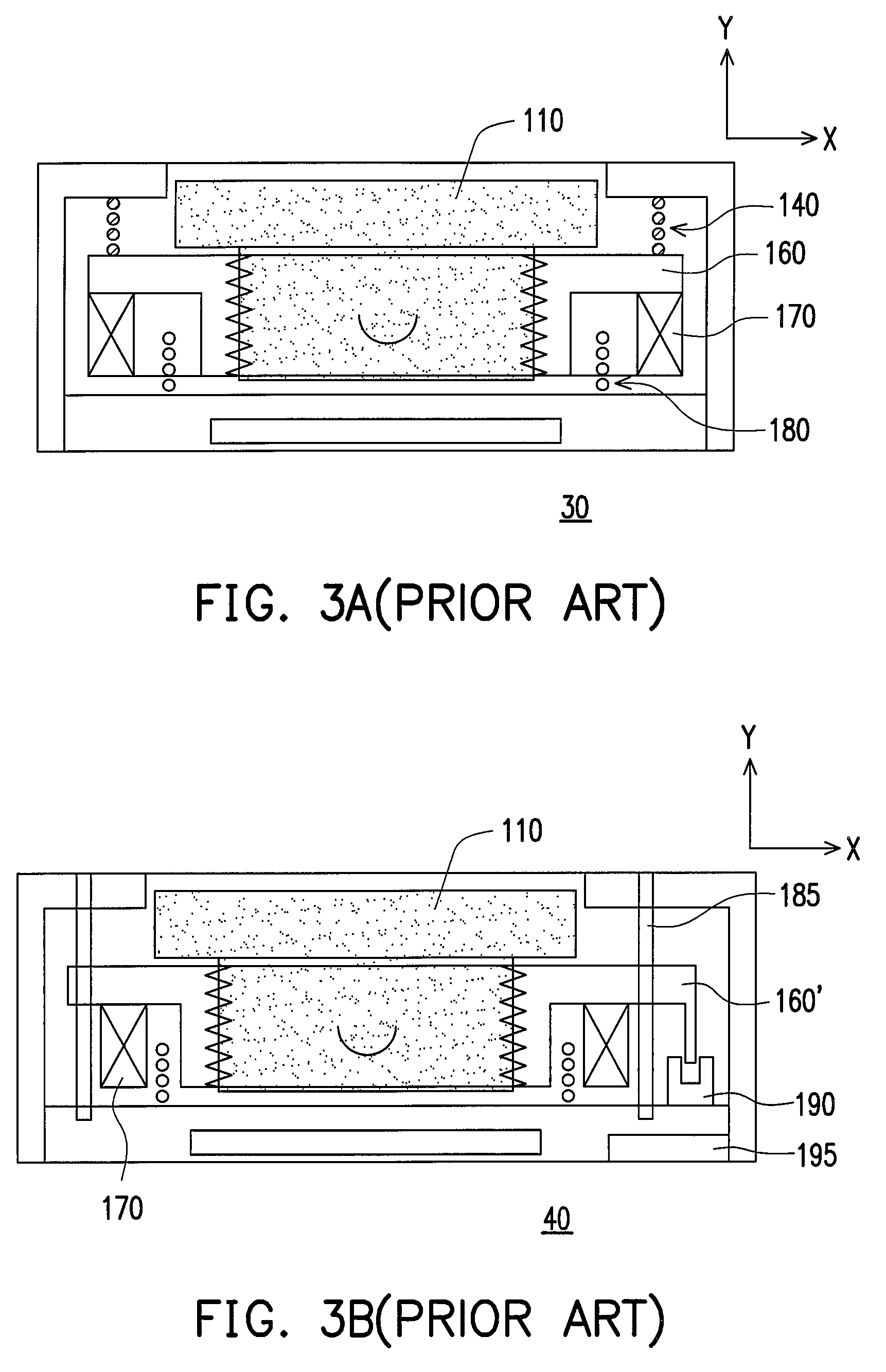
In addition, to fix the position of the lens 110 on axis X with electromagnetic force, the problem of the lens 110 being tilted may be caused.
Moreover, the performance of the lens module 30 in vibration test or falling test is not ideal.
It is noted that the manufacturing cost of the lens module 40 is high even though no current is continuously provided to the coil 180 after focusing.
However, the lens module 50 has only two-stage focusing function and the size thereof is large.
Moreover, the manufacturing cost of the lens module 50 is increased by the high cost of the annular magnet 196.

Method used


Image

  • Lens module
  • Lens module
  • Lens module

Examples


Embodiment Construction

[0031]In the following detailed description of the preferred embodiments, reference is made to the accompanying drawings which form a part hereof, and in which is shown by way of illustration specific embodiments in which the invention may be practiced. In this regard, directional terminology, such as “top,”“bottom,” etc., is used with reference to the orientation of the Figure(s) being described. The components of the present invention can be positioned in a number of different orientations. As such, the directional terminology is used for purposes of illustration and is in no way limiting. On the other hand, the drawings are only schematic and the sizes of components may be exaggerated for clarity. It is to be understood that other embodiments may be utilized and structural changes may be made without departing from the scope of the present invention. Also, it is to be understood that the phraseology and terminology used herein is for the purpose of description and should not be r...


PUM


Abstract

A lens module including a base, a sleeve, a lens, a magnetic permeable column, a coil supporter, a coil, and a magnet set is provided. A bottom of the base has a plurality of bumps. The sleeve is rotatably disposed on the bumps. The lens is disposed in the sleeve, and the magnetic permeable column is disposed beside the sleeve. The coil is disposed between two holes of the coil supporter. The magnetic permeable column is disposed through the holes and the coil. The magnet set is disposed beside the coil. The sleeve has a plurality of step portions and each bump contacts the corresponding step portion. When a current is provided to the coil, the electromagnetic force produced between the coil and the magnet set moves the coil along the magnetic permeable column, to push the coil supporter and accordingly rotate the sleeve coupled with the coil supporter.

Description

CROSS-REFERENCE TO RELATED APPLICATION[0001]This application claims the priority benefit of Taiwan application serial no. 95124440, filed Jul. 5, 2006. All disclosure of the Taiwan application is incorporated herein by reference.BACKGROUND OF THE INVENTION[0002]1. Field of the Invention[0003]The present invention relates to a lens module. More particularly, the present invention relates to a zoom lens module.[0004]2. Description of Related Art[0005]Referring to FIG. 1, in a conventional manual focusing lens module 10, a lens 110 is inserted into an internal ring 120, and the internal ring 120 is sustained between a focus-adjusting ring 130 and a spring 140. The focus-adjusting ring 130 has segmented steps, thus, when the focus-adjusting ring 130 is turned manually, the focus-adjusting ring 130 links the internal ring 120 and the lens 110 to move up and down along Y-axis to complete a focusing operation. However, the lens module 10 is not convenient to use because it focuses manually...

Claims


Application Information

Patent Timeline
Patent Type & Authority Patents(United States)
IPC IPC(8): G02B7/02G02B15/14
CPCH02K41/0356G02B7/102
Inventor WU, CHIH-MENGCHOU, TUNG-HUAMENG, CHI-YU
Owner YOUNG OPTICS
Why Eureka
Try Eureka