Graphical user interface and method and electronic device for navigating in the graphical user interface

a graphical user interface and user interface technology, applied in the field of mobile telecommunication systems, can solve the problems of increasing the difficulty of presenting the poor perception of the current position within the material, and the small display not being the best place to present a large amount of information

Active Publication Date: 2008-07-29
APPLE INC
View PDF10 Cites 42 Cited by
  • Summary
  • Abstract
  • Description
  • Claims
  • Application Information

AI Technical Summary

Benefits of technology

[0012]The present invention has several advantages over the prior-art solutions. The present invention helps navigation and orientation in a virtual desktop, when the virtual desktop area is larger than the visible area on a display.

Problems solved by technology

A small display is not the best place to present a large amount of information.
Even if scroll bars are not used, there still are drawbacks with the present solutions.
The biggest problem is that when the material to be presented on the display is considerably larger than the display area, the current location within the material is not well perceived.
The situation becomes even more difficult when the user is allowed to use a zoom function.
There are, however, several problems with the prior-art solutions.
The problem with the scroll bars is that they need a certain amount of display space, the space already being limited.
The problem is the same when presenting the coordinates numerically.
Coordinates do not promote quick navigation.
So, it may very hard for the user quickly to perceive the exact location on the virtual desktop.
Therefore, it is for example difficult to return to a certain active area of the operating system, where specific functions or activities are started by activating, e.g. objects or icons.
Moreover, it is difficult to move from an application to another on the virtual desktop if the accurate location of the destination application is not clear.

Method used


Image

  • Graphical user interface and method and electronic device for navigating in the graphical user interface
  • Graphical user interface and method and electronic device for navigating in the graphical user interface
  • Graphical user interface and method and electronic device for navigating in the graphical user interface

Examples


Embodiment Construction

[0019]Reference will now be made in detail to the embodiments of the present invention, examples of which are illustrated in the accompanying drawings.

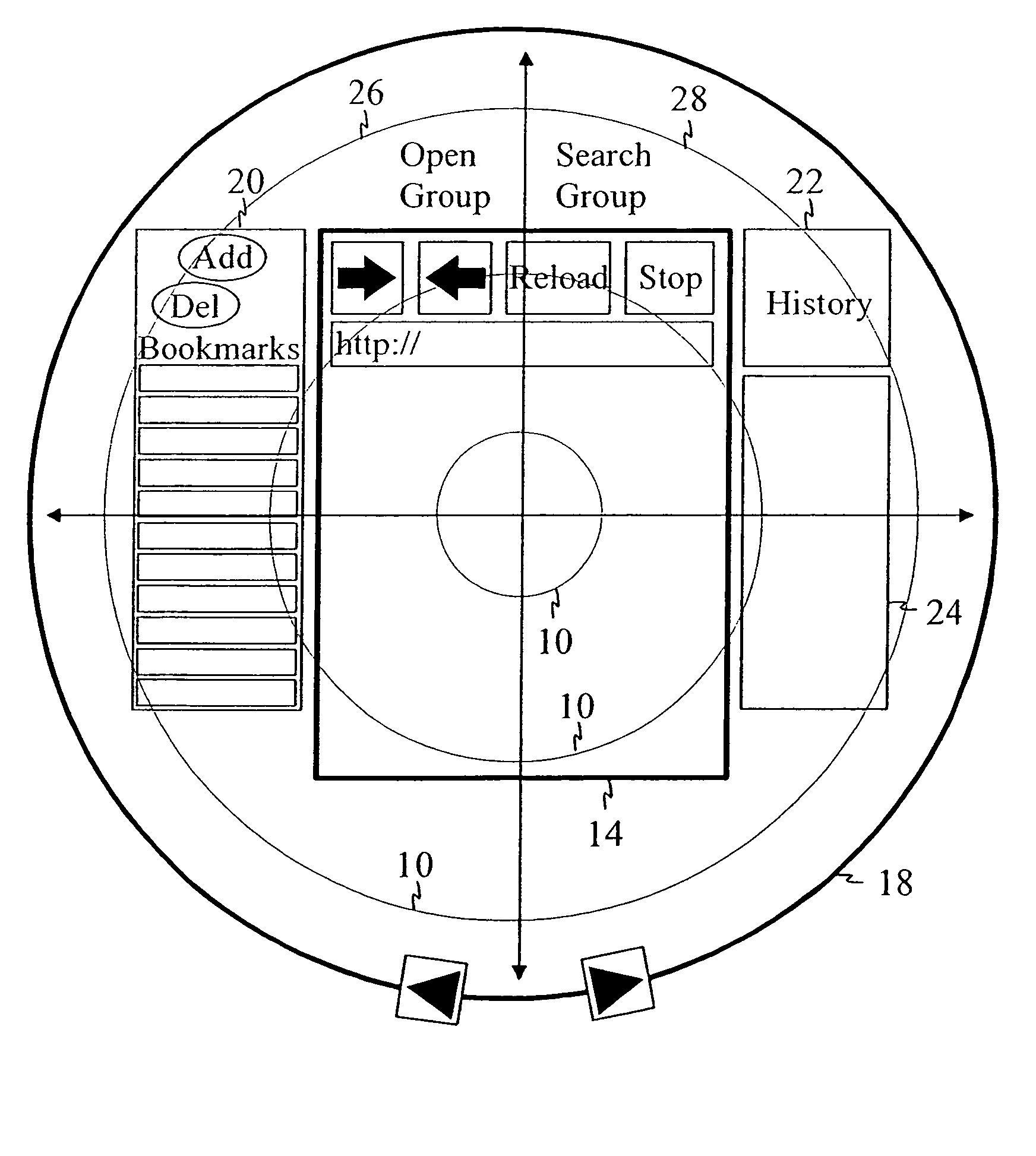
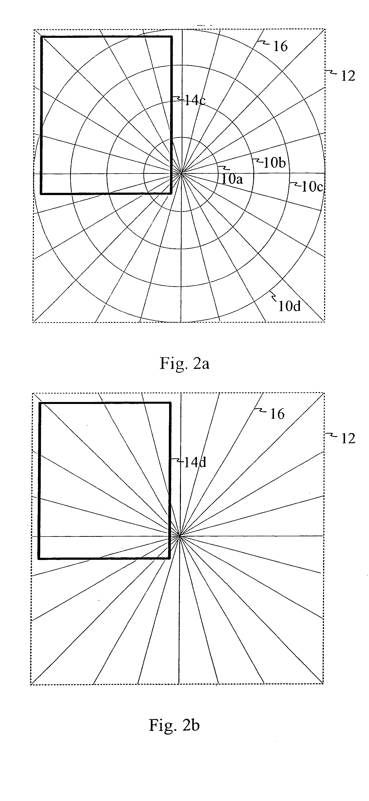
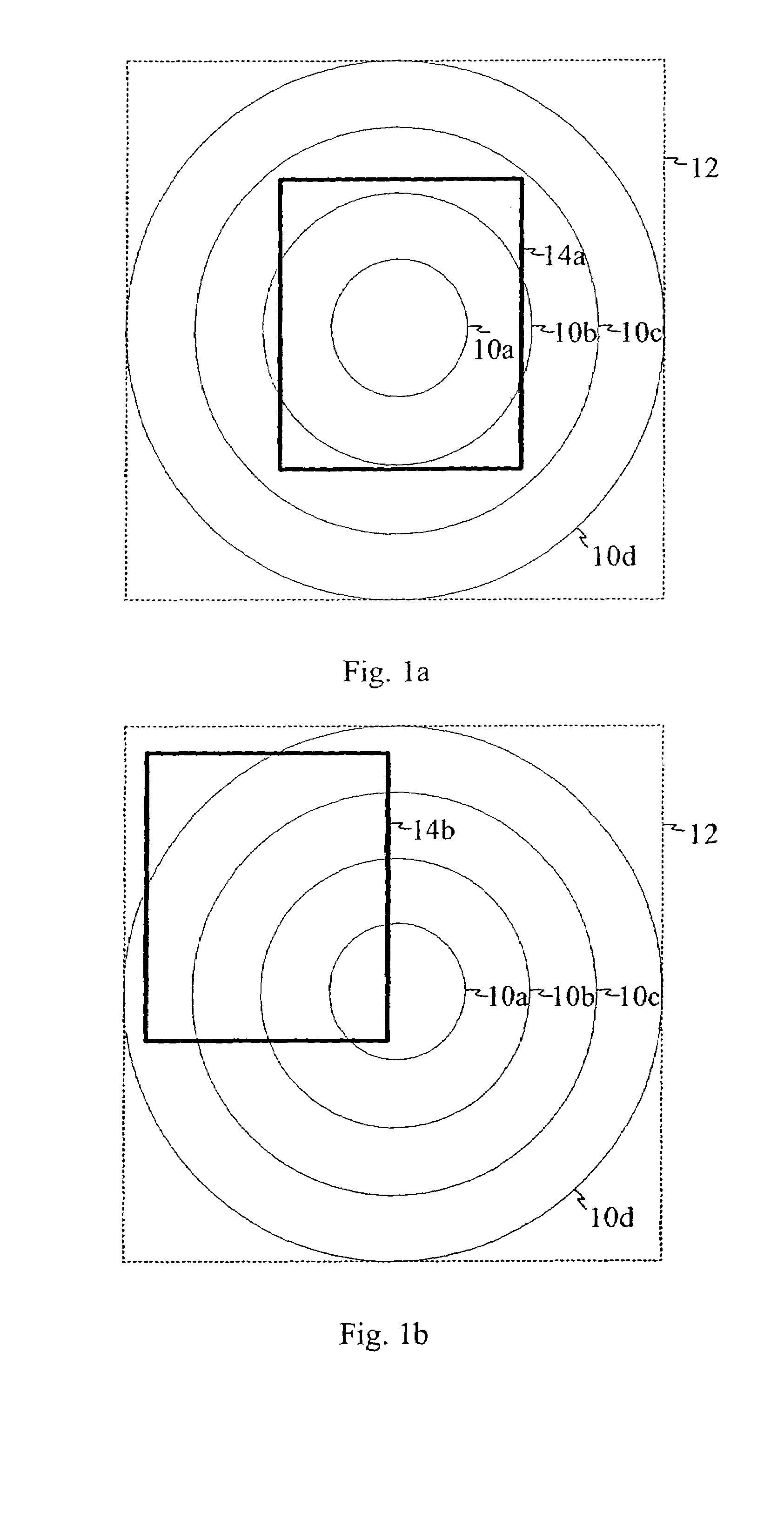
[0020]FIGS. 1a, 1b, 2a and 2b illustrate embodiments of the guiding lines. The area 12 represents the user interface area or virtual desktop being considerably larger than the visible display area. The areas 14a, 14b, 14c and 14d represent the visible areas of the display. In FIGS. 1a, 1b and 2a, there are concentric circles 10a . . . 10d acting as guiding lines. It is very easy to observe based on the circles where the point of origin is. If the curvature degree of the visible part of a circle is strong, it means that the point of origin is not far away. Vice versa, if the curvature degree of the visible part of a circle is not so strong, it means that there is certain distance to the point of origin.

[0021]In one embodiment of FIG. 1a, the concentric guiding lines are replaced with elliptic lines.

[0022]FIGS. 2a and 2b comprise radial...


PUM


Abstract

A method, graphical user interface and electronic device for forming guiding lines in a graphical user interface of an electronic device comprising at least a display and a navigating device, wherein a potion of the virtual desktop area of the graphical user interface is seen on the display at a time. In the method, digital material is placed on the virtual desktop area. The method further comprises the steps of determining a point of origin within the digital material and defining at least two points through which a guiding line is drawn, the guiding line indicating the distance and / or direction to the point of origin. The guiding line is then displayed along with the digital material on the display.

Description

RELATED APPLICATION[0001]This is a continuation of International Application No. PCT / FI03 / 00315, filed Apr. 17, 2003.BACKGROUND OF THE INVENTION[0002]1. Field of the Invention[0003]The present invention relates to mobile telecommunication systems. In particular, the present invention relates to a novel and improved graphical user interface, method and electronic device for forming guiding lines in a graphical user interface of an electronic device[0004]2. Description of the Related Art[0005]The size of the display of an electronic device sets certain limits for presenting, e.g. digital information on the display. A small display is not the best place to present a large amount of information. If all of the information is presented on the display at a time, details become illegible. A solution to this problem is that a so-called virtual desktop is used. There the actual view of the digital information is (much more) greater than the size of the display device. Therefore, means for scr...

Claims


Application Information

Patent Timeline
Patent Type & Authority Patents(United States)
IPC IPC(8): G06F13/00G06F15/00G06F1/16G06F3/0481G06F3/0485
CPCG06F1/1613G06F1/1626G06F1/1694G06F3/0485G06F3/0481G06F2203/04806G06F2200/1637
Inventor VAANANEN, JOHANNESMETSAVAINIO, JUKKA-PEKKAHARTOJOKI, ANNA-LEENA
Owner APPLE INC
Why Eureka
Try Eureka