Motor-driven position adjustment apparatus for steering wheel

a technology of position adjustment apparatus and steering wheel, which is applied in the direction of power driven steering, fluid steering, vehicle components, etc., can solve the problems of reducing the forward displacement of the steering wheel b>8/b>, disadvantage from the aspect of satisfactory protection of the driver, and difficulty in ensuring the concentricity of the driving rod, so as to improve the protection of the driver

Inactive Publication Date: 2008-08-12
NSK LTD
View PDF18 Cites 57 Cited by
  • Summary
  • Abstract
  • Description
  • Claims
  • Application Information

AI Technical Summary

Benefits of technology

[0028]In the case of a motor-driven position adjustment apparatus for a steering wheel of the present invention constructed as described above, even if the driving member is not a two-piece construction (even if it is a one-piece construction), it can allow the steering column to be displaced by a shock load applied at the time of a collision. Therefore, it is possible to ensure silence during position adjustment, and also achieve an improvement in the protection of a driver at the time of a collision.

Problems solved by technology

However, to the degree that the steering column 1 does not contract, not only does the peak of the shock load tend to occur at the initial stage of the secondary collision, but also the amount of forward displacement of the steering wheel 8 is reduced, and hence it is a disadvantage from the aspect of satisfactory protection of the driver.
However, it is difficult to ensure the concentricity of the driving rod 5a comprising the outer casing 10 and the internal shaft 11, over its full length.
If it becomes eccentric, a non-uniform force acts on the part where the male thread 6 of the driving rod 5a and the nut screw together, and when rotating the driving rod 5a in order to adjust the fore-aft position of the steering wheel 8, annoying grinding noises, and uncomfortable vibrations are likely to occur.
However, in the case where such a structure is used, it is difficult to design to ensure the reliability (difficulty of breaking) of the threaded part of the male thread of the driving rod and the nut, and also to break the female thread reliably during the secondary collision.

Method used


Image

  • Motor-driven position adjustment apparatus for steering wheel
  • Motor-driven position adjustment apparatus for steering wheel
  • Motor-driven position adjustment apparatus for steering wheel

Examples


example 1

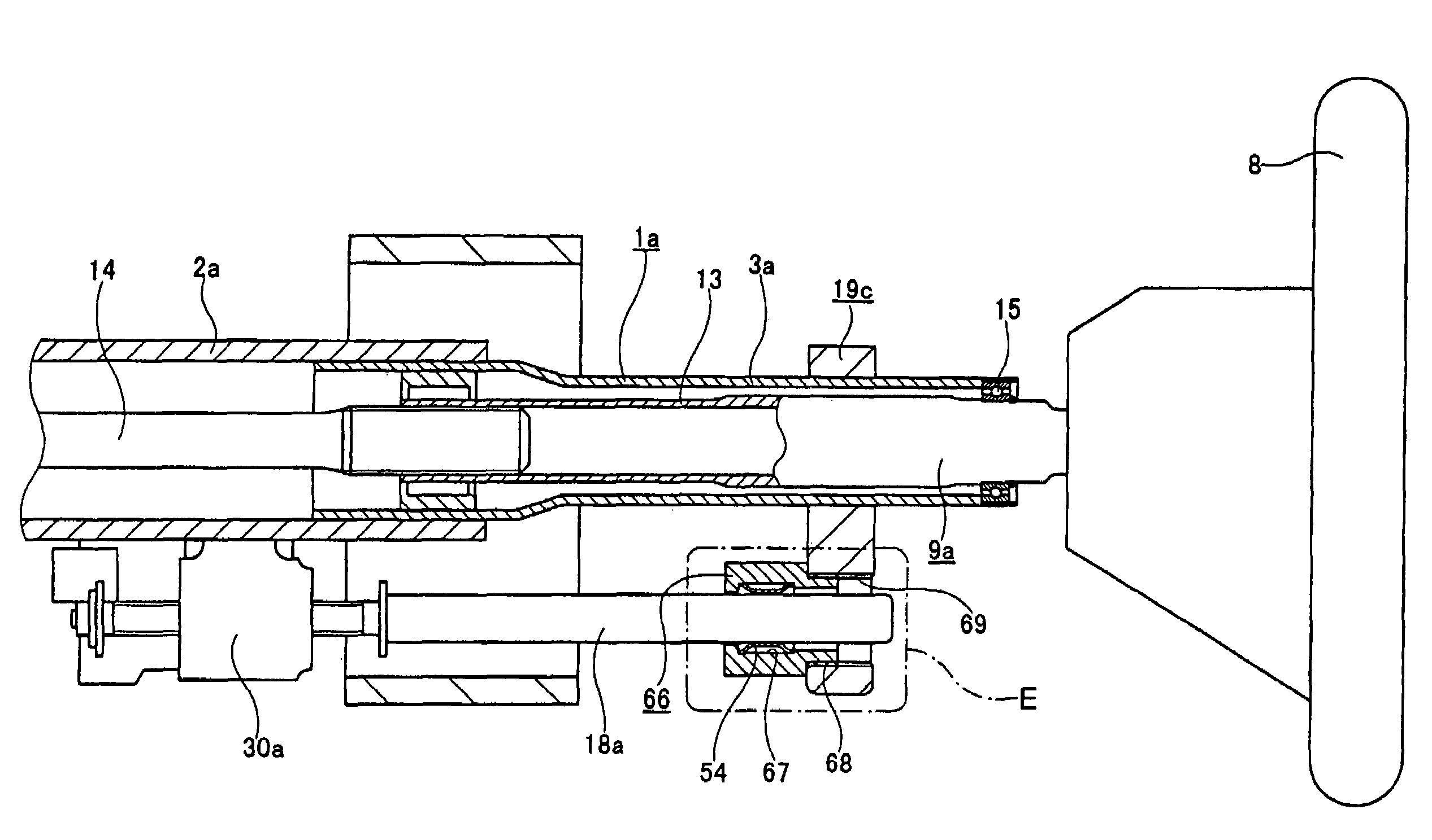
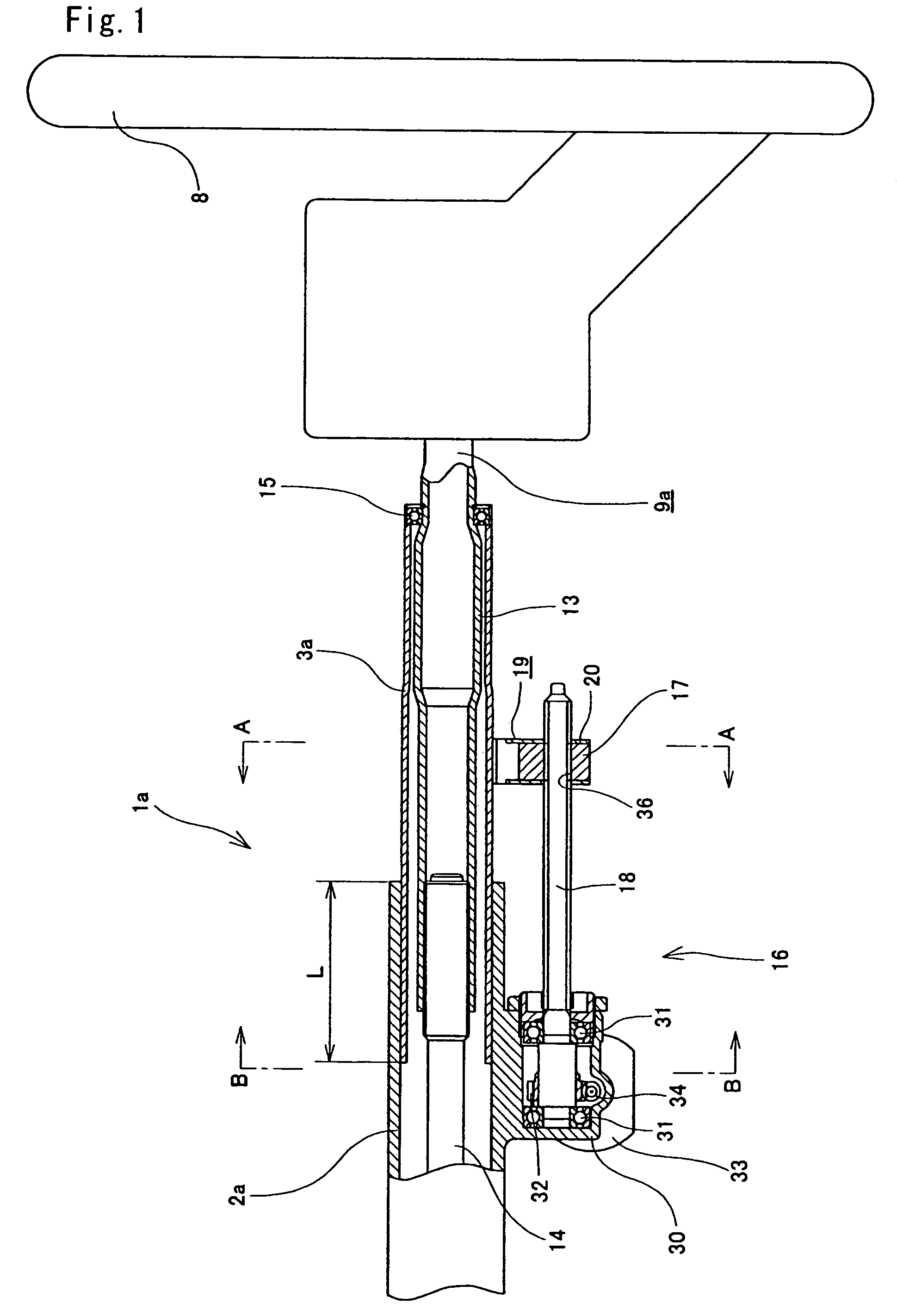
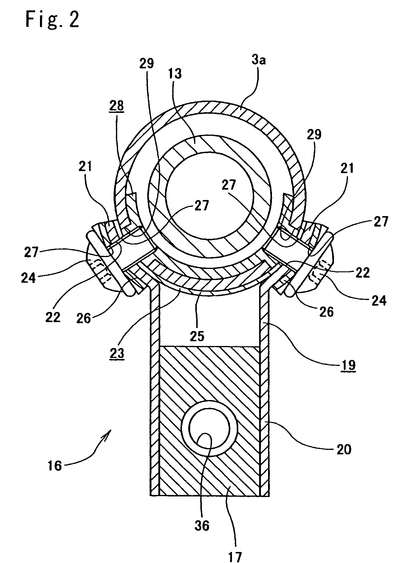
[0085]FIGS. 1 to 5 show example 1 of the present invention. The present example shows the case in which the present invention is used in a telescopic steering apparatus for adjusting the fore-aft position of a steering wheel 8. The steering wheel 8 is supported and fixed on a part, being the rear end part of the steering shaft 9a, that protrudes backward from the rear end part (right end part in FIGS. 1 and 4) of the steering column 1a. The steering column 1a is a telescopic steering column whose overall length can be extended and contracted by inserting the front part of an inner column 3a provided toward the rear (right side in FIGS. 1 and 4) into the rear part of an outer column 2a provided toward the front (left side in FIGS. 1 and 4) such that they fit with each other without loose and they can slide to each other in the axial direction. Such a steering column 1a extends and contracts by its full length by changing an engagement length L of the outer column 2a and the inner col...

example 2

[0095]FIG. 6 shows example 2 of the present invention. In the case of the present example, the top end parts of a pair of joining plates 35 are screwed to the bottom surface of an inner column 3a in a state in which the two joining plates 35 hang down from the bottom surface of the inner column 3a. Moreover a rectangular shaped nut 17a constituting a feed screw mechanism 16 (refer to FIGS. 1, 4 and 5 regarding overall structure) is supported between the lower halves of the two joining plates 35 by a pair of screws 24a such that it can be detached by a shock load. Therefore, regarding the nut 17a used in the present example, in addition to the threaded hole 36 for constituting the feed screw mechanism 16, a second threaded hole 37 is formed in a torsional direction (left / right direction above the threaded hole 36) turned perpendicular to the threaded hole 36.

[0096]The two screws 24a that are inserted through mounting holes 22a formed in the central parts of the two joining plates 35 ...

example 3

[0098]FIG. 7 shows example 3 of the present invention. In the case of the present example, similarly to the case of example 1 described previously, a rectangular shaped nut 17, being the driven member, is retained and fixed in a joining bracket 19. A pair of flange parts 21a provided on the top half part of the joining bracket 19 is supported on the outer peripheral surface of the inner column 3a constituting a telescopic steering column, via two joining members 39. The two joining members 39 are formed from a synthetic resin such as a polyamide resin, polyacetal resin or the like. A plurality of round rod shaped projections 40 is provided on the internal circumference side faces of the two joining members 39. The projections 40 of each of the two joining members 39 are inserted through holes 41 formed in the inner column 3a in a state in which the two internal circumference side faces butt up against the two side parts of the bottom surface of the inner column 3a. Furthermore the t...


PUM


Abstract

In a motor-driven steering wheel position adjustment apparatus, a nut 17 being a driven member is mounted such that it can be detached from an inner column of a steering column, based on a shock load applied at the time of a secondary collision, and therefore a threaded rod of a feed screw mechanism does not have resistance with respect to displacement of the inner column in the forward direction at that time. Improvement in the protection of a driver at the time of a collision can thus be achieved, and, since an integrated member can be used for the threaded rod, silence during the position adjustment of a steering wheel by the feed screw mechanism can be ensured.

Description

TECHNICAL FIELD[0001]This invention relates to improvements to a motor-driven steering wheel position adjustment apparatus which adjusts the position (either one or both of the fore-aft position and the up-down position) of a steering wheel using an electric motor as its power source. To be specific, it realizes a structure that can ensure silence during position adjustment, and that can achieve an improvement in the protection of a driver at the time of a collision accident.BACKGROUND ART[0002]A position adjustment apparatus of a steering wheel, such as a fore-aft position adjustment apparatus called a telescopic steering apparatus, or an up-down position adjustment apparatus called a tilt-type steering apparatus, is widely used as an apparatus for adjusting the position of a steering wheel according to the physical dimensions and posture of a driver. Furthermore, conventionally, a motor-driven position adjustment apparatus for a steering wheel is also widely used, in which the pos...

Claims


Application Information

Patent Timeline
Patent Type & Authority Patents(United States)
IPC IPC(8): B62D1/00
CPCB62D1/19B62D1/181
Inventor SAWADA, NAOKIIWAKAWA, MASATOSHODA, AKIHIROFUJIWARA, TAKESHI
Owner NSK LTD
Why Eureka
Try Eureka