Decorative light system

a technology of decorative light and light source, which is applied in the direction of special purpose vessels, lighting support devices, and with built-in power, etc., can solve the problems of overly difficult and expensive manufacturing, limited application of known devices, and inability to meet the requirements of lighting devices

Inactive Publication Date: 2008-08-12
SC JOHNSON & SON INC
View PDF292 Cites 43 Cited by
  • Summary
  • Abstract
  • Description
  • Claims
  • Application Information

AI Technical Summary

Problems solved by technology

However, there are deficiencies associated with each of the foregoing lighting devices.
For example, the known devices have limited applications and are overly difficult and expensive to manufacture.
In addition, none of the known devices have communications capabilities to provide a control center remotely from the decorative lighting device.
Still further, none of the known systems include multiple lighting devices that are wirelessly synchronized to present a coordinated light show.

Method used


Image

  • Decorative light system
  • Decorative light system
  • Decorative light system

Examples


Embodiment Construction

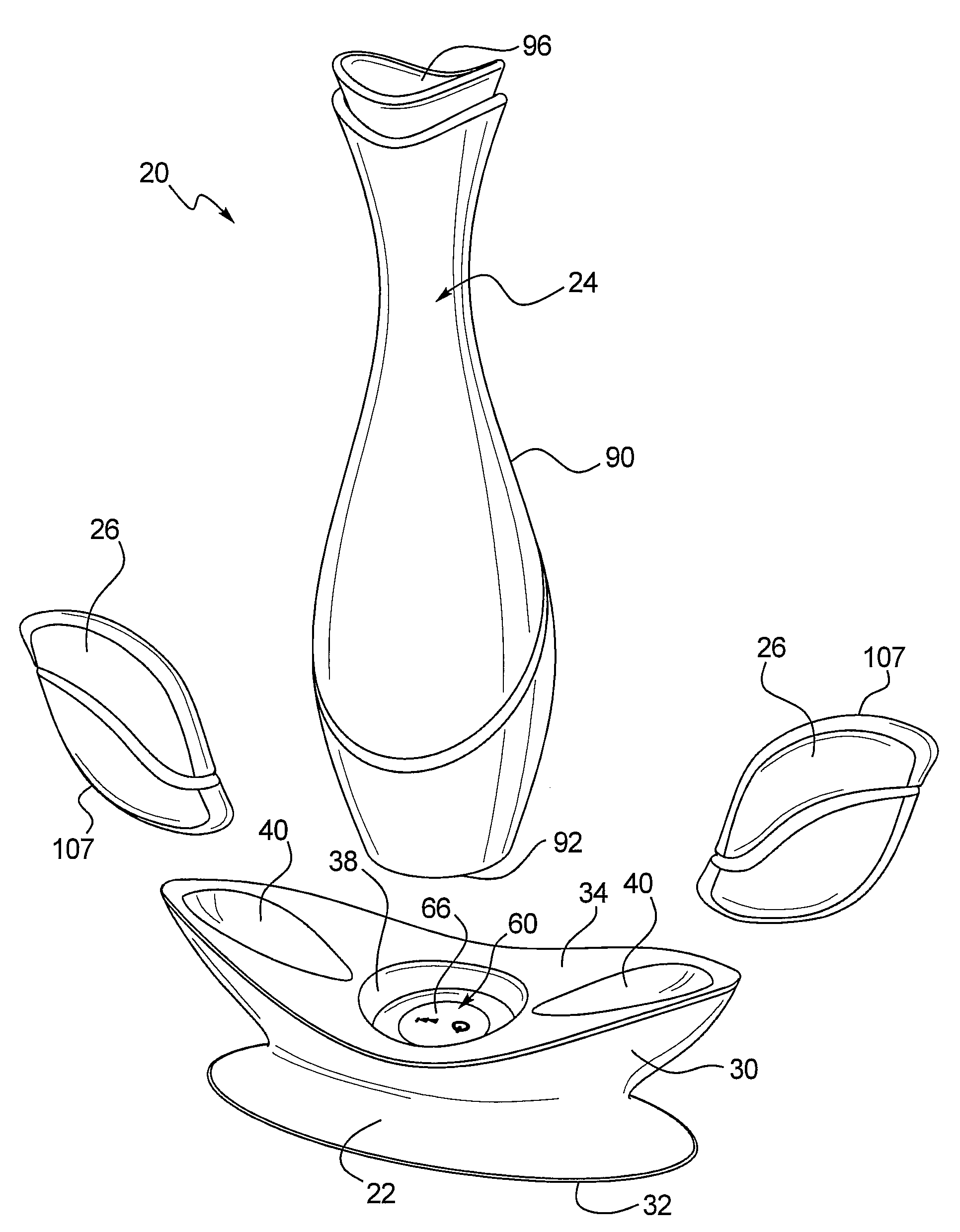
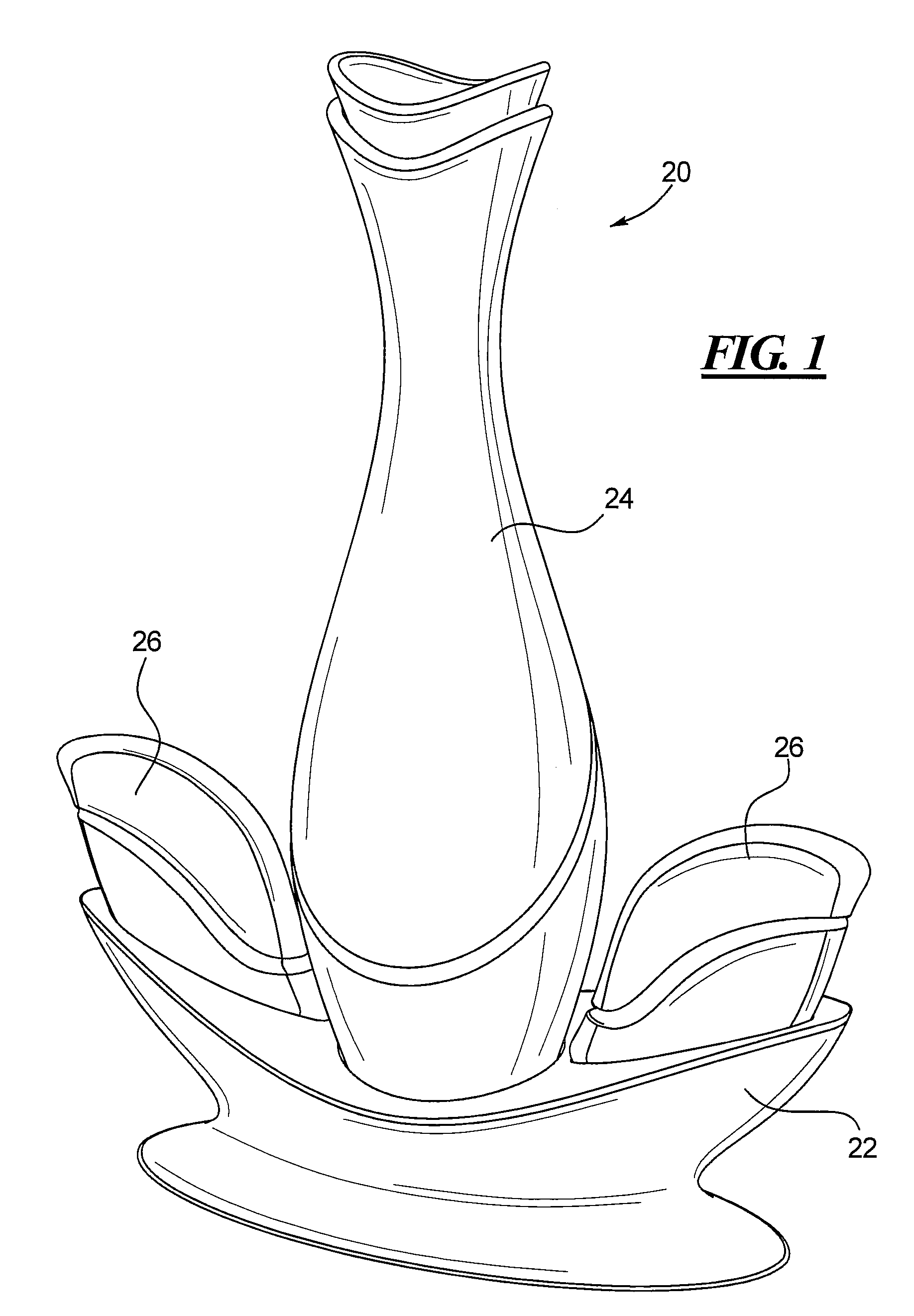
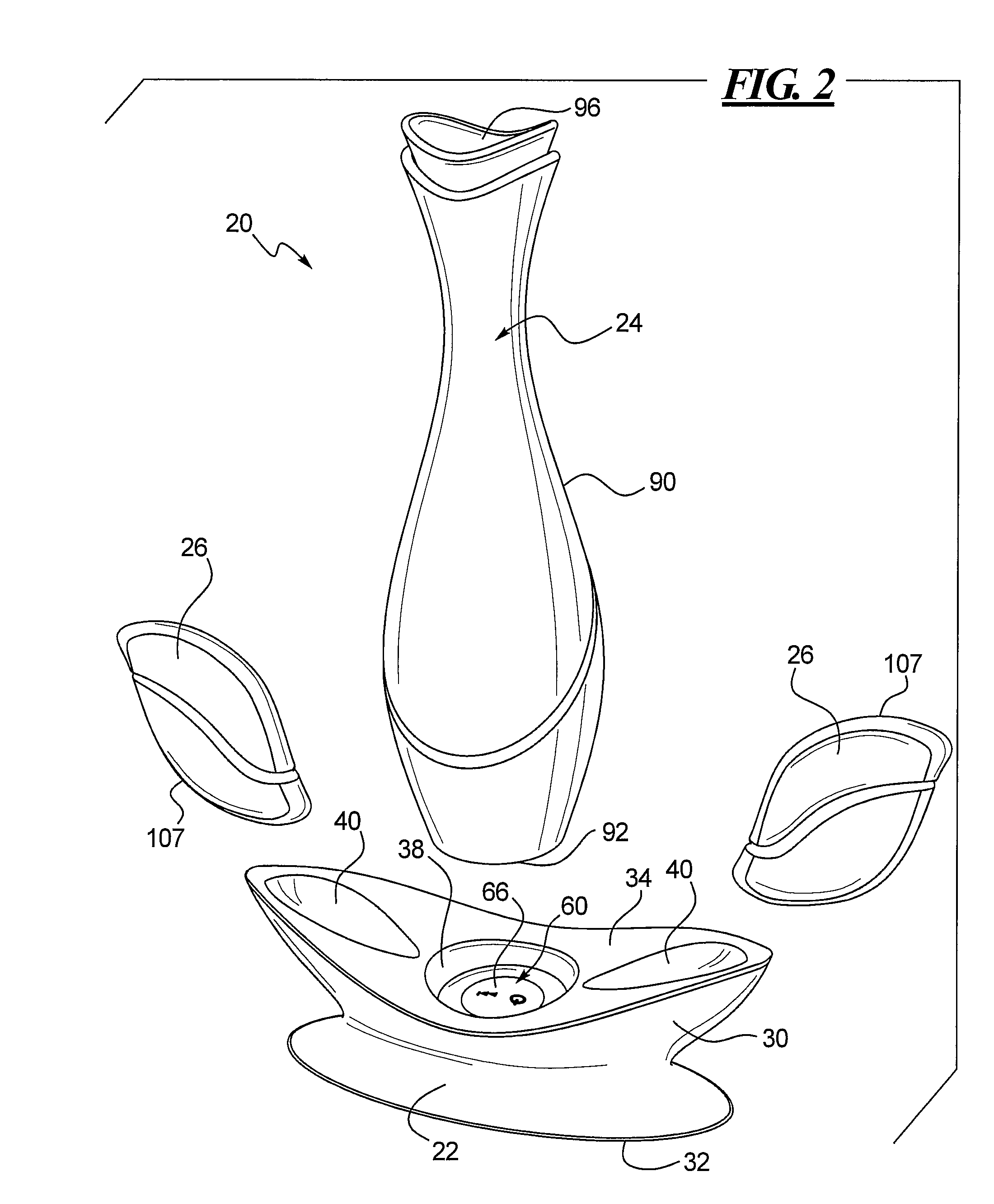
[0029]Various decorative light system embodiments are disclosed herein including one or more lighted objects removably engageable with a base. In certain embodiments, the base includes a light that illuminates an object placed adjacent thereto In other embodiments, the lighted object includes an illuminating device that is operated by controls stored in the base. In one embodiment, the lighted objects may include a storage vessel and at least one floating light object. This embodiment is particularly suited for use with a bathtub, where the storage vessel may contain soap, bath oil, or another product associated with the bath and the floating light object may be placed in the bath tub. In other embodiments, the decorative light system includes a base and one or more portable light devices that may or may not be buoyant. The base and portable light devices may include communications components to execute a coordinated light show, as discussed more fully below.

[0030]As used herein, el...


PUM


Abstract

A decorative light system includes a base and a portable light device capable of communicating with each other to generate a light show. The system includes a base defining a receptacle and including a microcontroller, a transceiver operably coupled to the microcontroller and adapted to generate a control signal, a first power source operably coupled to the microcontroller, and a user interface operably coupled to the microcontroller and including at least one switch for activating the microcontroller. The portable light device has a lower end sized for removable insertion into the base receptacle and includes a housing having at least a portion formed of a translucent material, a first receiver disposed within the housing and responsive to the control signal transmitted by the base transceiver, a first light source disposed within the housing, operably coupled to the receiver, and adapted to direct light toward the translucent portion of the housing, and a second power source disposed within the housing and operably coupled to the light source.

Description

CROSS-REFERENCE TO RELATED APPLICATION[0001]This application claims the benefit of U S. Provisional Application No 60 / 804,073, filed on Jun. 6, 2006, the entire disclosure of which is incorporated herein by reference.BACKGROUND[0002]1. Technical Field[0003]The present disclosure generally relates to decorative light systems, and mole particularly to decorative light systems used as home furnishings.[0004]2. Description of the Related Art[0005]Various decorative illuminated objects are known in the art, which display one or more lighting effects. For example, U.S. Pat. No. 6,801,003 (“Schanberget”) discloses lighting systems for swimming pools, wall-mounted lighting systems, and window-mounted light-systems that include a processor that is configured to control a color-changing lighting effect generated by the lighting apparatus. Schanberget discloses that the lighting system may also include memory storing one or more lighting programs and / or data. The lighting systems may also incl...

Claims


Application Information

Patent Timeline
Patent Type & Authority Patents(United States)
IPC IPC(8): F21V33/00
CPCH05B39/00H05B37/0272H05B37/029F21L4/08F21S9/02F21S10/02F21V23/0435F21Y2101/02F21W2121/00F21Y2115/10H05B47/19H05B47/155H05B45/28H05B45/20
Inventor HARRITY, KEVINCONWAY, SIMON M.FATERIOUN, KAMRANHEATHCOCK, SARAH E.ABBONDANZIO, MATTHEWDEMAREST, SCOTT W.WALTER, SCOTT D.DIR, RONALD R.HORTON, EDWIN T.
Owner SC JOHNSON & SON INC
Why Eureka
Try Eureka