Ratcheting winch tool

a technology of ratcheting winch and tool, which is applied in the direction of flexible elements, packaging, cargo supporting/securing components, etc., can solve the problem of inefficient manual rotation of straps, and achieve the effect of efficient tightening of tie-down straps and minimal effor

Inactive Publication Date: 2008-08-12
MCGREW DAVID L
View PDF9 Cites 57 Cited by
  • Summary
  • Abstract
  • Description
  • Claims
  • Application Information

AI Technical Summary

Benefits of technology

[0007]Accordingly, the instant invention presents a tool that permits a user to tighten tie-down straps efficiently and with a minimum of effort. The invention provides for improved elements thereof in an arrangement for the purposes described that are inexpensive, dependable and fully effective in accomplishing their intended purposes.

Problems solved by technology

This manual rotation is a very inefficient means for tightening the straps.

Method used


Image

  • Ratcheting winch tool
  • Ratcheting winch tool
  • Ratcheting winch tool

Examples


Embodiment Construction

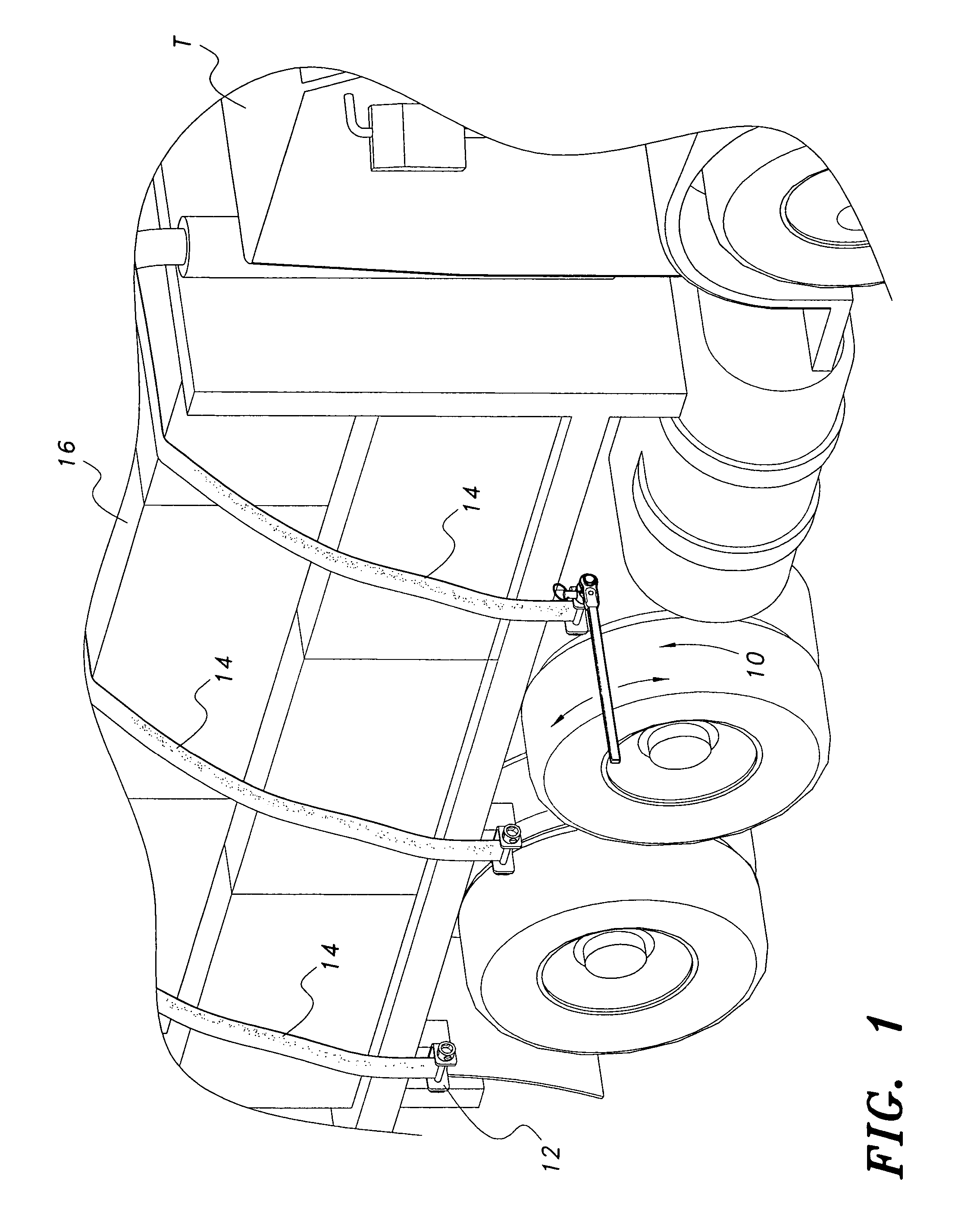
[0013]Attention is first directed to FIG. 1 wherein the tool of the present invention is generally indicated at 10. As illustrated, tool 10 is mounted on a winch 12 to tighten a strap 14, which strap functions to secure cargo 16 disposed on a flat bed truck T. As indicated above, tool 10 would be successively mounted on each of the winches 12 to tighten each strap.

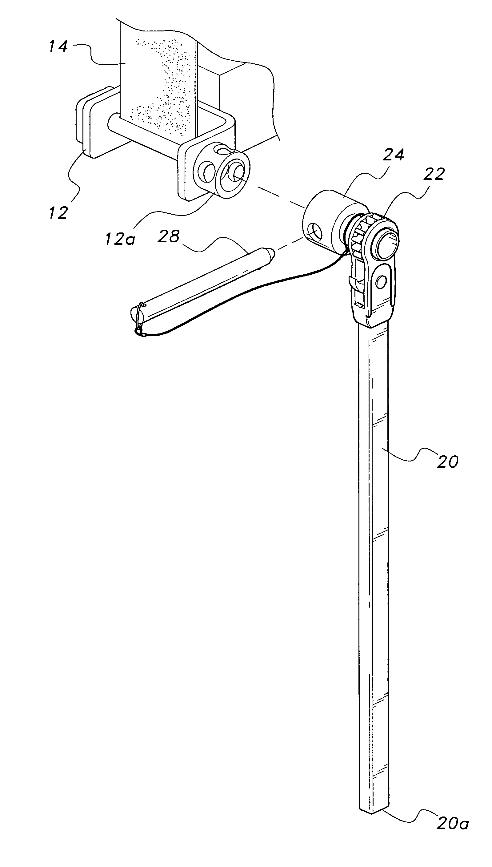
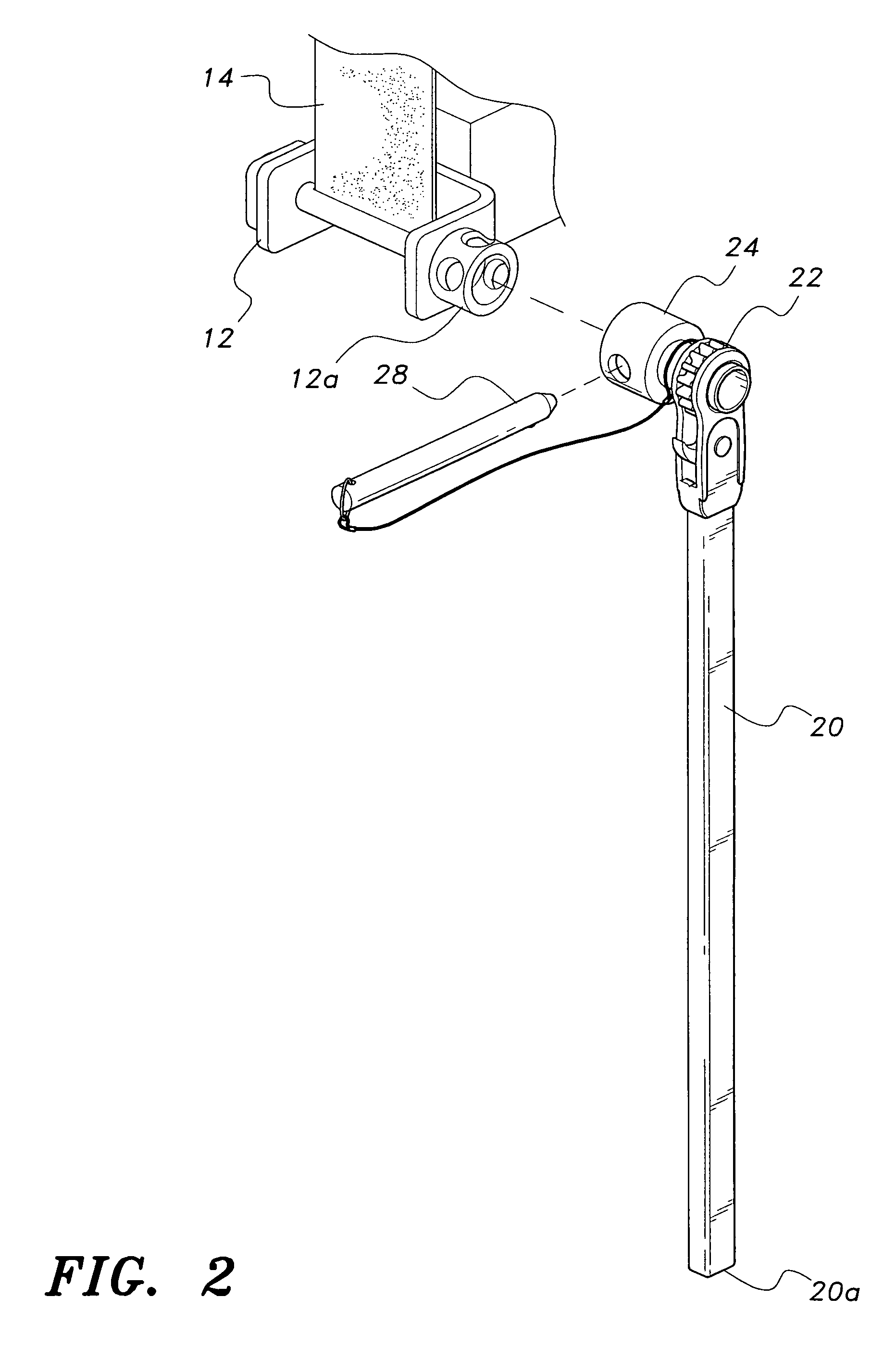
[0014]As best seen in FIGS. 2 and 3 tool 10 comprises a handle 20 having a proximate end and a distal end 20a. Distal end 20a is a free end. The proximate end is terminates in a ratchet mechanism 22. Handle 20 is fabricated from standard ¾″ metal stock. Although the handle may be made to any convenient length, it has been found that a handle length of about 27″ is most suitable. A cylindrical socket 24 extends from one side of ratchet mechanism 22. Socket 24 is defined by a cylindrical wall having an open end and having diametrically positioned openings 26 formed therethrough. Cylindrical socket 24 is adapted to encompass ...


PUM


Abstract

A tool adapted to tighten tie-down straps utilized to secure cargo transported on flatbed trailers or the like. The tool includes an elongate handle having a standard ratchet mechanism fixed at one end thereof. A cylindrical socket extends from one side of the ratchet mechanism. The cylindrical socket is designed to encompass a conventional winch drive shaft. Diametrically spaced openings are formed in the circumferential wall of the socket for receiving a locking pin therethrough. The cylindrical socket could be configured internally, at least, to match the winch drive shaft with which it will be used, e.g., square, hexagonal, etc.

Description

BACKGROUND OF THE INVENTION[0001]1. Field of the Invention[0002]The present invention generally relates to hand tools. More specifically, the present invention is drawn to a ratchet wrench employed to tighten tie-down straps that secure cargo on flat bed trailers and the like.[0003]2. Description of the Related Art[0004]It is conventional in the hauling and transporting industry to utilize straps (usually fabricated from nylon) to tie down cargo being transported on flat bed trucks or similar vehicles. Typically, one end of the strap(s) is secured in place on one side of the truck bed. The strap is then disposed over the cargo and the opposite end of the strap is inserted into a winch located on the opposite side of the truck bed. The winch is then rotated in a direction to tighten the strap and secure the cargo. This procedure is followed for each strap used in the arrangement. A bar is employed to rotate the winch. The bar is inserted in the winch and is manually rotated until the...

Claims


Application Information

Patent Timeline
Patent Type & Authority Patents(United States)
IPC IPC(8): B65D63/18
CPCB60P7/0853
Inventor MCGREW, DAVID L.
Owner MCGREW DAVID L
Why Eureka
Try Eureka