Multiple circuit receptacles

Active Publication Date: 2008-08-12
BYRNE NORMAN R
View PDF7 Cites 54 Cited by
  • Summary
  • Abstract
  • Description
  • Claims
  • Application Information

AI Technical Summary

Benefits of technology

[0031]The outlet receptacle block can include latch means. The power supply means can comprise at least one junction block having tab means. The latch means and the tab means can cooperate so as to prevent the receptacle circuit means from inadvertently releasing from the junction block in the absence of any externally exerted forces on the outlet receptacle block, when the receptacle means is electrically coupled to the junction block. The latch means can include locking latches positioned on top and bottom portions of the outlet receptacle block, with each of the locking latches being of a resilient construction. The tab means can comprise an upstanding tab, so that when the outlet receptacle block is first brought into position to be electrically coupled to the junction block, the tab exerts upwardly directed forces on at least one of the locking latches, thereby causin

Problems solved by technology

Such conventional and stationary wall-mounted systems were often located a substantial distance from the electrical devices to be energized and numerous electrical cords connecting the devices to the outlets would cause unsightly and sometimes dangerous entanglements.
Again, however, such units resulted in unsightly and entangled arrays of electrical device cords.
Any particular electrical circuit is limited to carrying a finite power load.
Further, however, having the availability of mul

Method used


Image

  • Multiple circuit receptacles
  • Multiple circuit receptacles
  • Multiple circuit receptacles

Examples


Embodiment Construction

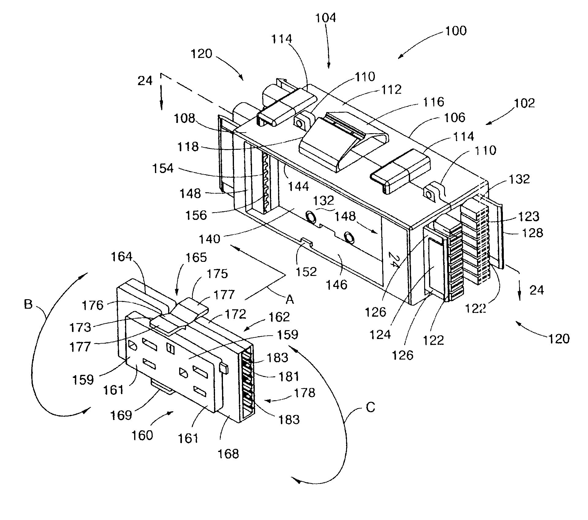
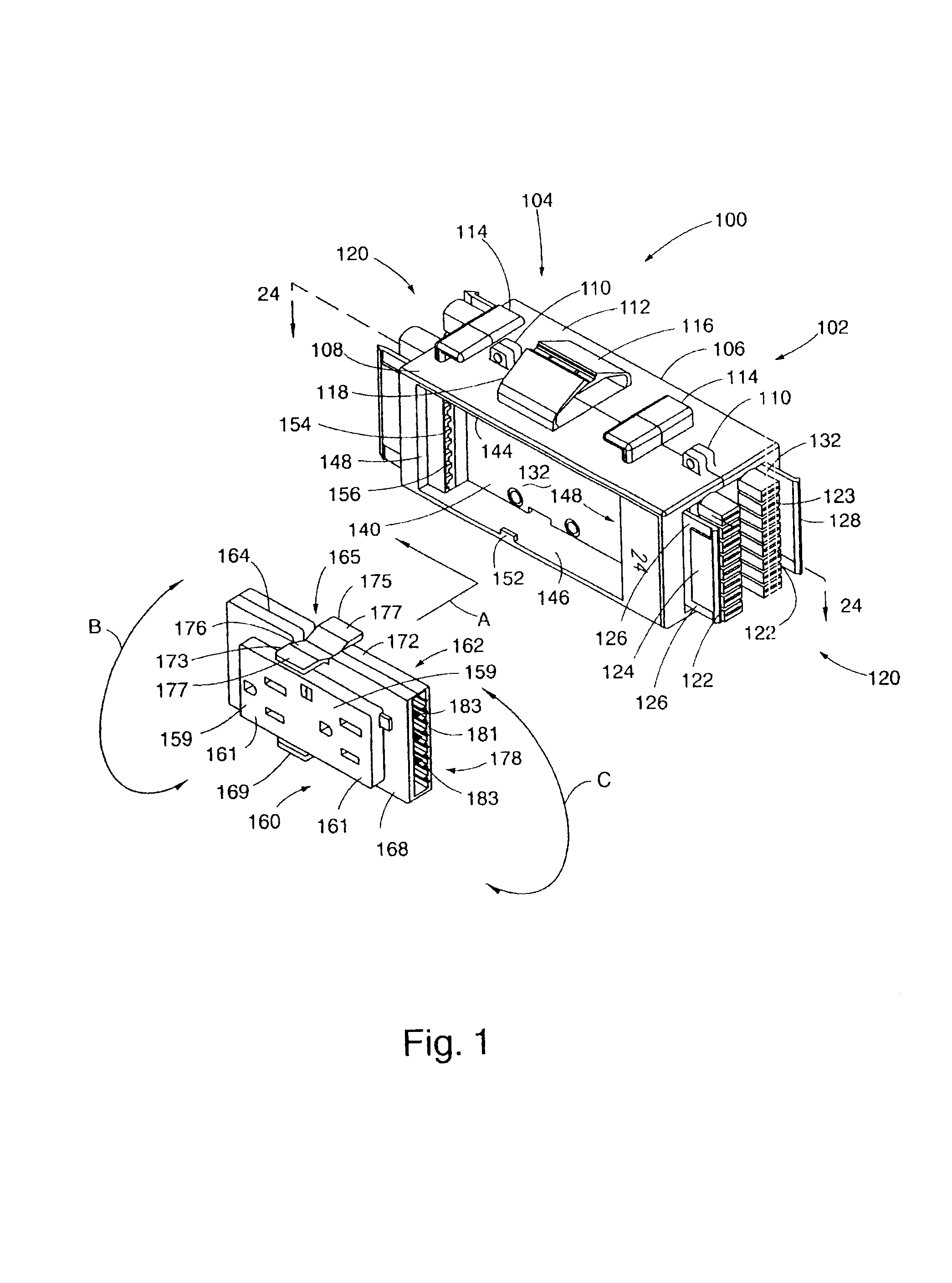
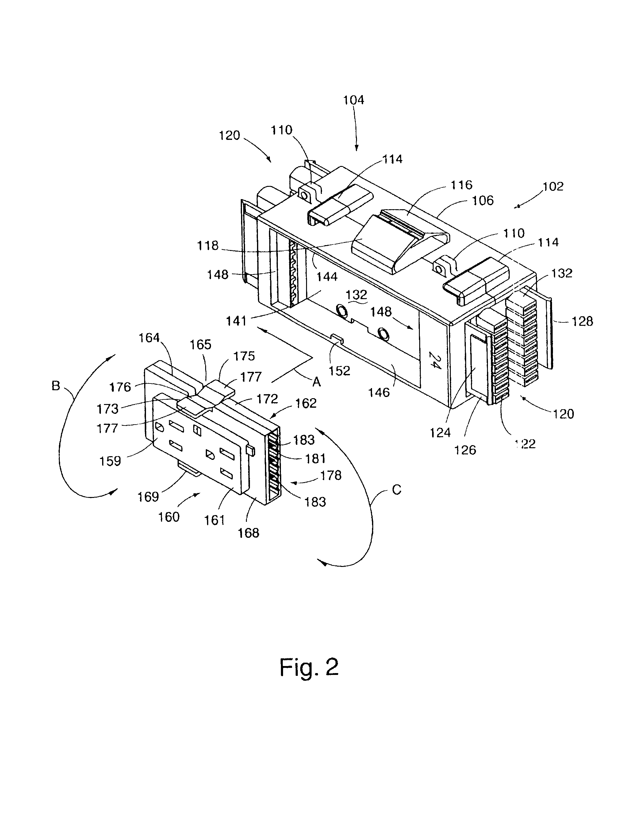
[0059]The principles of the invention are disclosed, by way of example, in a multiple circuit receptacle system 100 as described in subsequent paragraphs herein and illustrated in FIGS. 1-25. The multiple circuit receptacle system 100, in accordance with the invention, provides for the presentation, at outlet receptacles of an outlet receptacle block, of a selected one of a plurality of power supply circuits, and changing to a different selected one of the plurality of power supply circuits, without requiring the use of any tools, multiple receptacle blocks, multiple junction blocks, any changes in structure or physical orientation of junction blocks, or any additional elements, such as circuit adapters or the like. Instead, circuit selection is achieved by reconfiguring the physical orientation of the outlet receptacle block, relative to its interconnection to a power supply junction block. In the particular embodiment disclosed herein, an 8-wire system is described, with the capab...


PUM


Abstract

A multiple circuit receptacle system (100) is disclosed. The receptacle system (100) includes a junction block (102) having an incoming female connector set (122) adapted to be engaged with a cable assembly (180) for supplying incoming power to the junction block (102). He junction block (102) also has a further female connector set (154), electrically coupled to the incoming female connector set (122), through which power is supplied from the cable assembly (180). The incoming power is in the form of four separate circuits, each circuit having hot, neutral and ground terminals. An electrical outlet receptacle block (160) includes a series of outlet receptacles (159) and connector sets (179, 181) selectively connectable to the further connector set (154) of the junction block (102). Connection of the receptacle block (160) to the junction block (102) in one of various spacial orientations provides for electrical power from any selected one of the multiple circuits to be presented at the outlet receptacles (159).

Description

CROSS-REFERENCE TO RELATED APPLICATIONS[0001]Not applicable.STATEMENT REGARDING FEDERALLY SPONSORED RESEARCH OR DEVELOPMENT[0002]Not applicable.REFERENCE TO A MICROFICHE APPENDIX[0003]Not applicable.BACKGROUND OF THE INVENTION[0004]1. Field of the Invention[0005]The present invention relates to electrical power systems and, more particularly, to arrangements for electrically interconnecting outlet receptacle blocks so as to provide for a selected one of a plurality of power supply circuits.[0006]2. Background Art[0007]The use of computers, associated computer peripherals (e.g. printers and the like), copiers, facsimile machines, sophisticated telecommunications equipment and other electronic devices is continuing to rapidly increase in commercial, industrial and office environments. As a result, the importance of efficiently supplying power throughout these environments is also increasing. For example, the use of modular office systems, with multiple workstations and interior walls,...

Claims


Application Information

Patent Timeline
IPC IPC(8): H01R25/16
CPCH01R13/652H01R24/78H01R29/00H01R31/065H01R25/164H01R13/508H01R2103/00
Inventor BYRNE, NORMAN R.
Owner BYRNE NORMAN R
Why Eureka
Try Eureka