Display system incorporating bilinear electromechanical grating device

a technology of electromechanical grating and display system, which is applied in the field of display system, can solve the problems of difficult to obtain alignment precision, source of undesirable image aberration, and particularly costly components, and achieve the effects of reducing the cost, and reducing the number of components

Inactive Publication Date: 2008-08-12
EASTMAN KODAK CO
View PDF14 Cites 14 Cited by
  • Summary
  • Abstract
  • Description
  • Claims
  • Application Information

AI Technical Summary

Benefits of technology

[0023]It is an advantage of the present invention that it provides a full-color imaging system, using linear arrays of electromechanical grating devices, where the system does not require alignment of individual color paths for modulated light.
[0024]It is an advantage of the present invention that it provides a full-color imaging system using linear arrays of electromechanical grating devices with a reduced number of components, allowing design of a more compact and lower cost apparatus than provided by earlier designs. With its reduced number of components and minimized requirements for adjustment, the apparatus of the present invention provides a robust solution for imaging using electromechanical grating array devices.

Problems solved by technology

This precision of alignment is difficult to obtain.
Color combiner 100 is a particularly costly component and can be the source of undesirable image aberrations.
However, as noted in the '425 Kowarz et al. disclosure, color-sequential techniques, by modulating only one color at a time, effectively waste two-thirds of the potentially available light.
Moreover, problems such as excessive flicker can result from the use of color-sequential techniques, particularly under various conditions of color content.
Thus, although color-sequential solutions minimize alignment concerns and provide a cost-reduced system, these solutions have performance drawbacks and limitations.

Method used


Image

  • Display system incorporating bilinear electromechanical grating device
  • Display system incorporating bilinear electromechanical grating device
  • Display system incorporating bilinear electromechanical grating device

Examples


Embodiment Construction

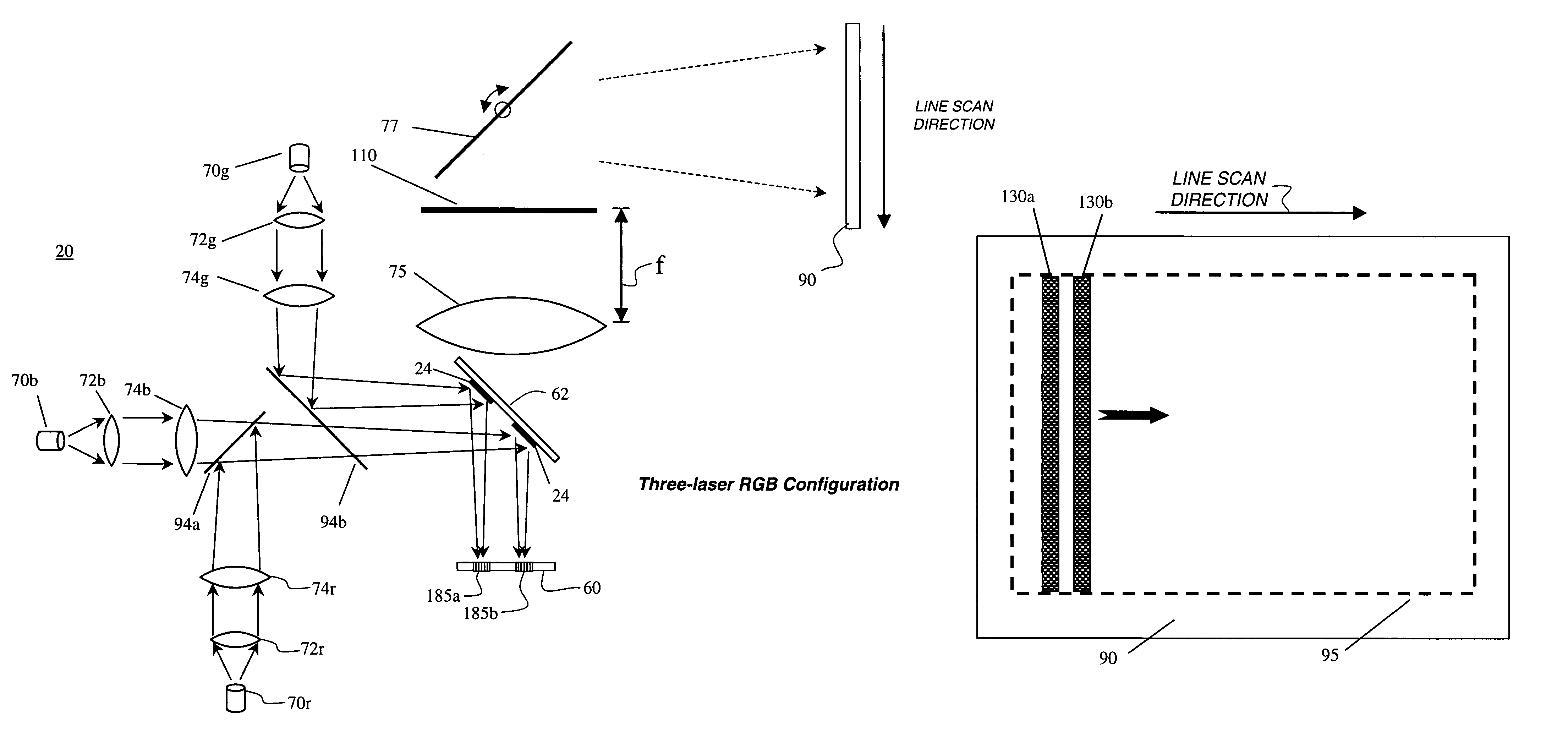
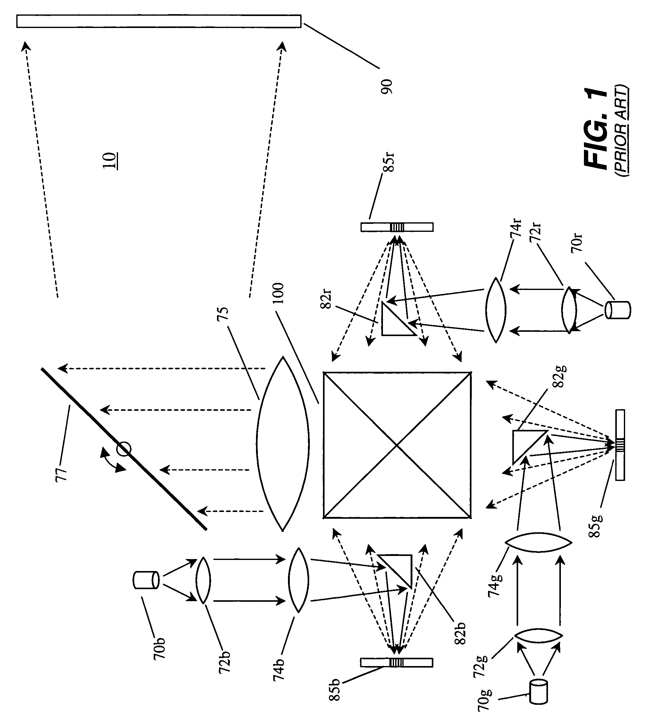
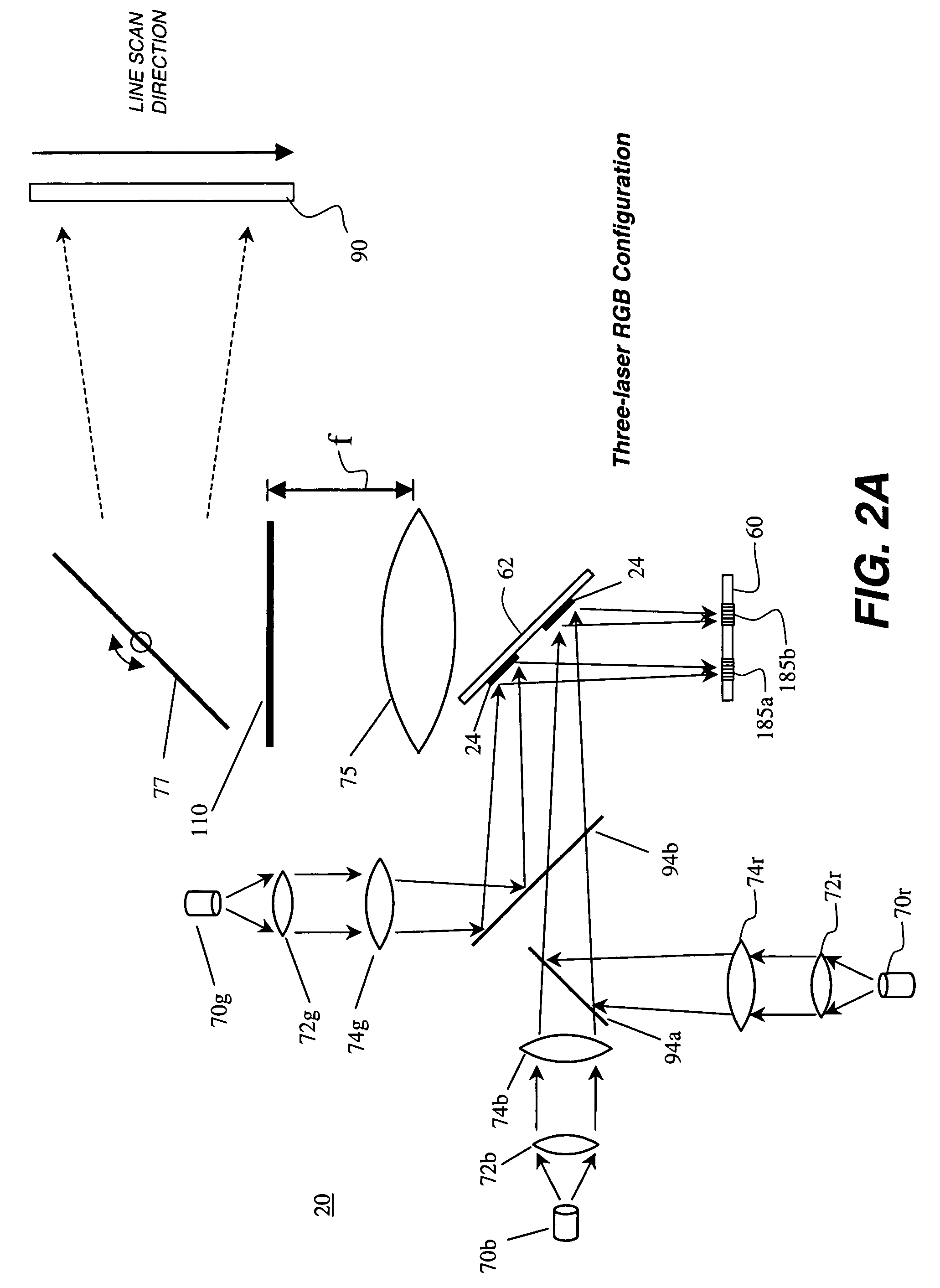
[0039]The present description is directed in particular to elements forming part of, or cooperating more directly with, apparatus in accordance with the invention. It is to be understood that elements not specifically shown or described may take various forms well known to those skilled in the art.

[0040]For the description that follows, components specific to a single color path may be more particularly identified with an letter appended to the part number. Where used, lower case letters correspond to the optical components for specific colors; for example, “r” is appended for red, “b” for blue, “g” for green, “y” for yellow. Upper case letters identify the colors themselves, for example, “R” is red, “B” is blue, “G” is green, “Y” is yellow, “M” is magenta, “C” is cyan, “O” is orange.

[0041]FIG. 2A is a schematic block diagram showing the arrangement of color modulation components in one embodiment of the present invention. This embodiment of display system 20 of the present inventio...


PUM


Abstract

A line scanned display system includes at least three different colors of illumination provided by one or more light sources, and at least one directional illumination optical system for directing the three different colors of illumination. Also in the system is a bilinear array, having two linear arrays of light modulating devices, situated on a common substrate for receiving and modulating two different colors of illumination at any one time that are obtained from the three different colors of illumination. Finally, a lens for creating line images of the two linear arrays on a screen and a scanning mirror for scanning the line images across the screen to form an area image complete the system.

Description

CROSS-REFERENCE TO RELATED APPLICATIONS[0001]This is a 111A application of U.S. Provisional Application Ser. No. 60 / 711,008, filed Aug. 24, 2005.FIELD OF THE INVENTION[0002]This invention relates to a display system with a linear array of light modulating devices that is scanned in order to generate a two-dimensional image. More particularly, the invention relates to a display system containing a bilinear array of electromechanical grating devices.BACKGROUND OF THE INVENTION[0003]Spatial light modulators based on electromechanical grating devices are important for a wide range of applications, including display, data storage, spectroscopy and printing. Such systems require large numbers of individually addressable devices in either a linear or area array, with over a million addressable devices desirable for an area modulator array in a high-quality display.[0004]Linear arrays are particularly advantaged over their area array counterparts by virtue of higher resolution, reduced cost...

Claims


Application Information

Patent Timeline
Patent Type & Authority Patents(United States)
IPC IPC(8): G02B26/08G03B21/00
CPCG02B26/0808G02B27/102H04N9/3132G02B27/143G02B27/149G02B27/104
Inventor KOWARZ, MAREK W.
Owner EASTMAN KODAK CO
Why Eureka
Try Eureka