
Mode locking methods and apparatus

a mode locking and apparatus technology, applied in the field of wave generation, can solve the problems of many industrial and technical applications, deficient source of electromagnetic radiation and resultant output wave characteristics with respect to a set of parameters, and many linewidth limitations plague other,

Active Publication Date: 2008-08-19
MASSACHUSETTS INST OF TECH
View PDF7 Cites 218 Cited by
  • Summary
  • Abstract
  • Description
  • Claims
  • Application Information

AI Technical Summary

Problems solved by technology

The source of the electromagnetic radiation and the resultant output wave characteristics are often deficient with respect to a set of parameters.
Linewidth limitations plague other wave sources.
As a result, many industrial and technical applications are limited by the wave generating component of the system.

Method used


Image

  • Mode locking methods and apparatus
  • Mode locking methods and apparatus
  • Mode locking methods and apparatus

Examples


embodiment 15

[0094]Without loss of generality, different laser cavity configurations can be used depending upon the properties of the devices used and optimization of desired performance characteristics of the laser. For example, the cavity embodiment 15 shown in FIG. 7 is appropriate for a filter operating in a transmission mode, such that desired wavelengths / frequencies are transmitted through the filter. Depending upon the type of filter used, the filter may have the property that light, which is not in the pass band, is retroreflected rather than transmitted. In this case, an isolator is required between the filter and the gain medium to prevent feedback of the unwanted light from the filter to the gain medium. The output coupler can be placed at various positions in the cavity depending upon the desired operation.

[0095]In FIG. 7, the output coupler OPC, such as an optical coupler, is positioned after the gain element or amplifier. This provides a higher power output since the intensity in t...

embodiment 22

[0105]The configuration of the linear cavity system 21 shown in FIG. 13 is appropriate for a filter F which operates by transmitting the desired wavelengths or frequencies. FIG. 14 shows another example of a linear cavity embodiment 22 which is suitable for use with a filter F which operates by retroreflecting the desired wavelengths or frequencies.

[0106]The linear cavity has some advantages compared to ring cavities which can be used to achieve optimum operation. For example, in the configuration 21 shown in FIG. 13, the light propagates through the filter twice per round trip. This enhances the filtering function provided by the filter. Since the light propagates through the fiber delay L twice, the length of fiber required for to achieve a given time delay is one half of that required in the ring cavity where the light propagates through the fiber once per round trip. In the geometry shown, the mirror M1 may also be a Faraday mirror or similar nonreciprocal reflecting element. Th...


PUM


Abstract

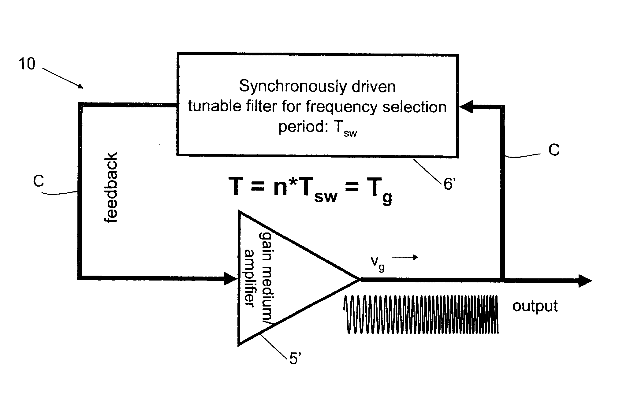
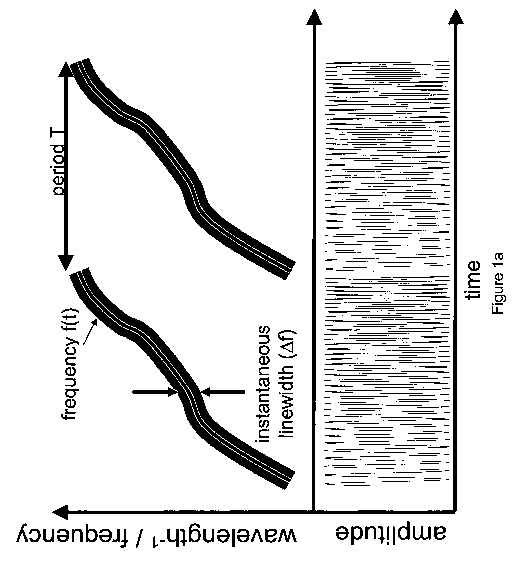
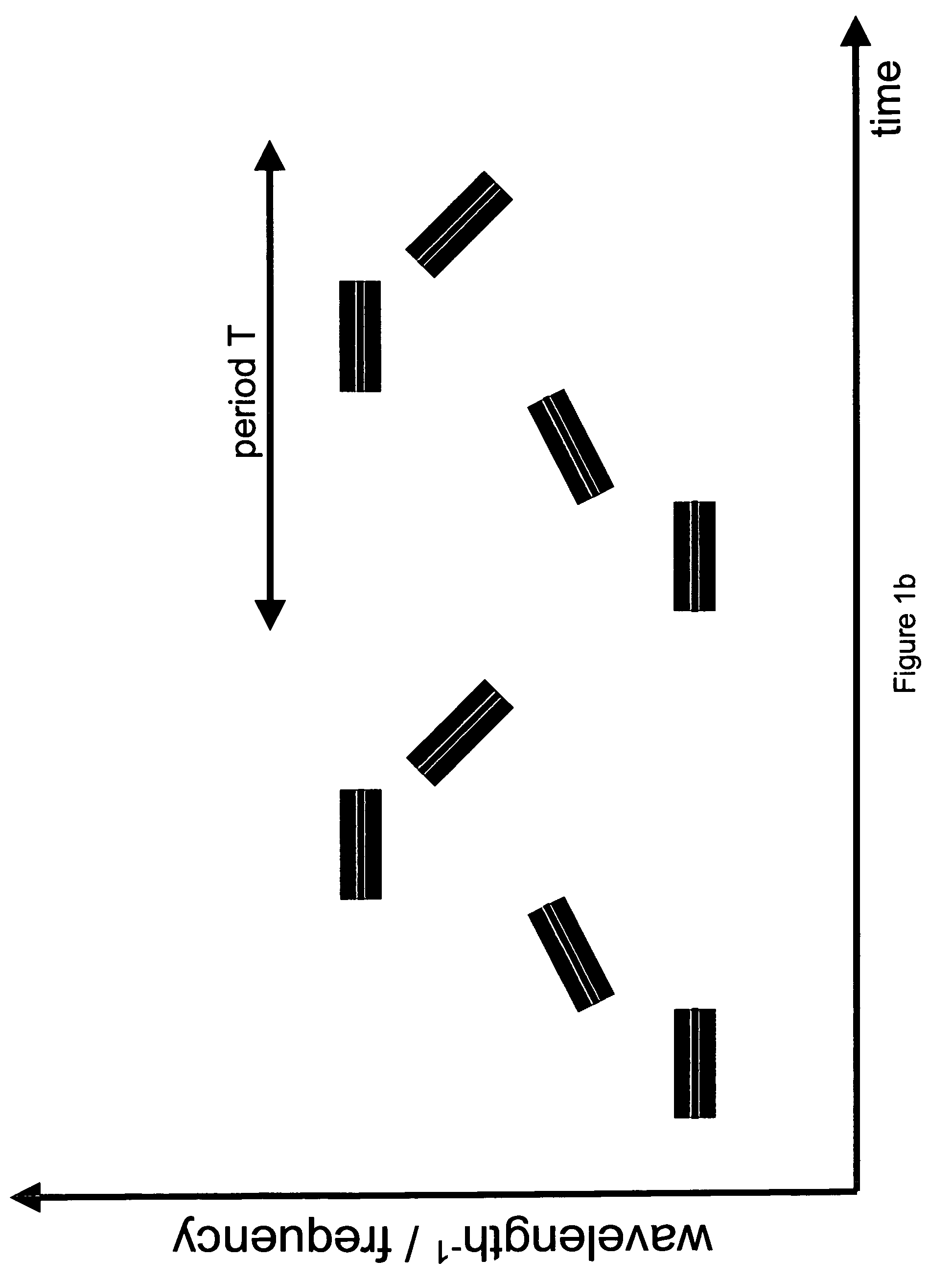
In one aspect the invention relates to a frequency varying wave generator. The generator includes a gain element adapted to amplify a wave having a wavelength; a time varying tunable wavelength selective filter element in communication with the gain element, the tunable filter element adapted to selectively filter waves during a period T; and a feedback element in communication with the tunable filter element and the gain element, wherein the tunable wavelength selective filter element, the gain element and the feedback element define a circuit such that the roundtrip time for the wave to propagate through the circuit is substantially equal to a non-zero integer multiple of the period T.

Description

RELATED APPLICATIONS[0001]This application claims priority to U.S. Provisional Patent Application 60 / 645,359 filed on Jan. 20, 2005, the disclosure of which is herein incorporated by reference in its entirety.GOVERNMENT SUPPORT[0002]This invention was made with government support under Grant Number ECS-0119452, awarded by NSF, Grant Number EY011289, awarded by NIH, and Grant Number FA9550-04-1-0046, awarded by the Air Force. The government has certain rights in the invention.FIELD OF THE INVENTION[0003]The invention relates generally to the field of wave generation. In particular, the invention relates to Fourier Domain Mode Locking (FDML) and applications thereof.BACKGROUND OF THE INVENTION[0004]In many industries and technical areas of research, various systems and devices are used to obtain precise measurements or imaging. In conjunction with the need for precision, there is also a demand for high speed data collection. To satisfy these two criteria, many wave-based technologies ...

Claims


Application Information

Patent Timeline
Patent Type & Authority Patents(United States)
IPC IPC(8): H01S3/00
CPCH01S3/106H01S3/1109H01S5/065G01B9/02004G01B9/02091G01B9/02069H01S3/063H01S3/08013H01S3/06725H01S3/06791H01S3/08027H01S3/083H01S3/1062H01S3/1068H01S3/107H01S3/1121H01S3/1305H01S3/2383H01S5/146H01S2301/08H01S3/082H01S3/1307H01S5/141H01S3/067
Inventor HUBER, ROBERTTAIRA, KENJIFUJIMOTO, JAMES
Owner MASSACHUSETTS INST OF TECH
Learn More