All-fiber pulsed laser

A pulsed laser and all-fiber technology, which is applied in the field of laser technology and nonlinear optics, can solve the problems of cumbersome adjustment steps, large insertion loss, and difficult manufacturing process, and achieve reduced manufacturing cost and process difficulty, high pulse energy, and compact structure Effect

Active Publication Date: 2013-11-27
BWT BEIJING
View PDF3 Cites 24 Cited by
  • Summary
  • Abstract
  • Description
  • Claims
  • Application Information

AI Technical Summary

Problems solved by technology

[0005] In order to solve the large insertion loss and low conversion efficiency caused by adding acousto-optic and electro-optic modulation devices into the resonator; at the same time, semiconductor saturable absorption mirror (SESAM), carbon nanotube (SWNT) and graphene are used for Q-switching. Due to problems such as difficult manufact

Method used


Image

  • All-fiber pulsed laser
  • All-fiber pulsed laser
  • All-fiber pulsed laser

Examples


Embodiment 1

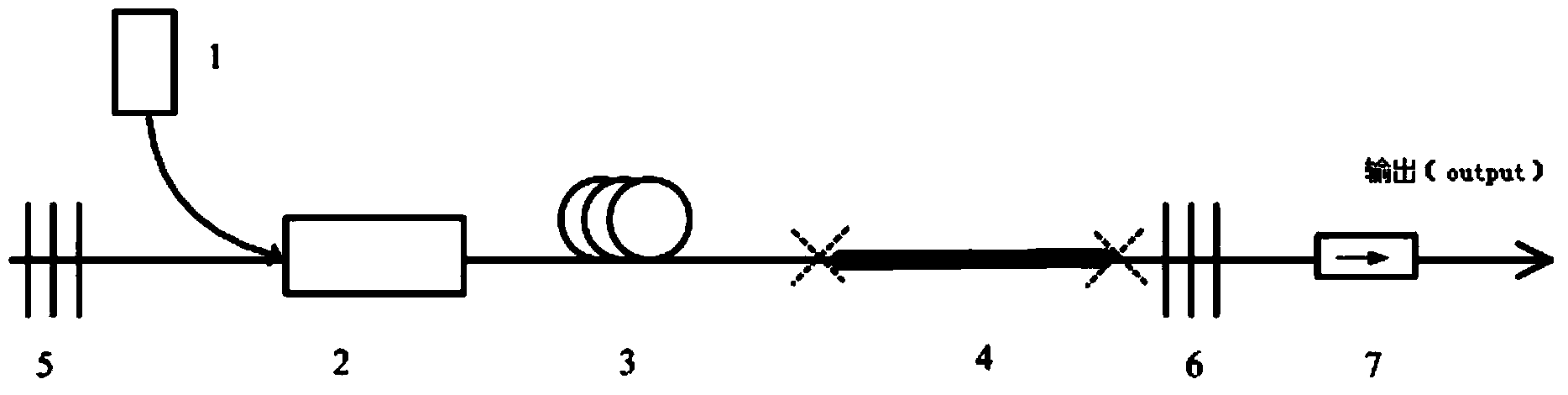
[0025] An all-fiber pulsed laser structure such as figure 1 shown. 1 in the figure is the pump source, which can be a semiconductor laser diode with a center wavelength of 976nm; 2 is a fiber beam combiner, and a (2+1)×1 pump signal beam combiner can be used, such as 6 / 125 or 20 / Type 125; 3 and 4 are rare-earth-doped optical fibers, and high-performance ytterbium-doped optical fibers produced by Nufern Company in the United States can be selected; 5 and 6 are reflective fiber Bragg gratings, which can be either full-reflection or partial reflection gratings, and the reflectivity is R. Among them, 0

[0026] The pumping light enters the first gain fiber 3 through the pump end of the fiber combiner 2, then reaches the second gain fiber 4 that can absorb saturably, and then reaches the second reflective fiber Bragg grating 6, whose reflectivity is R (0

Embodiment 2

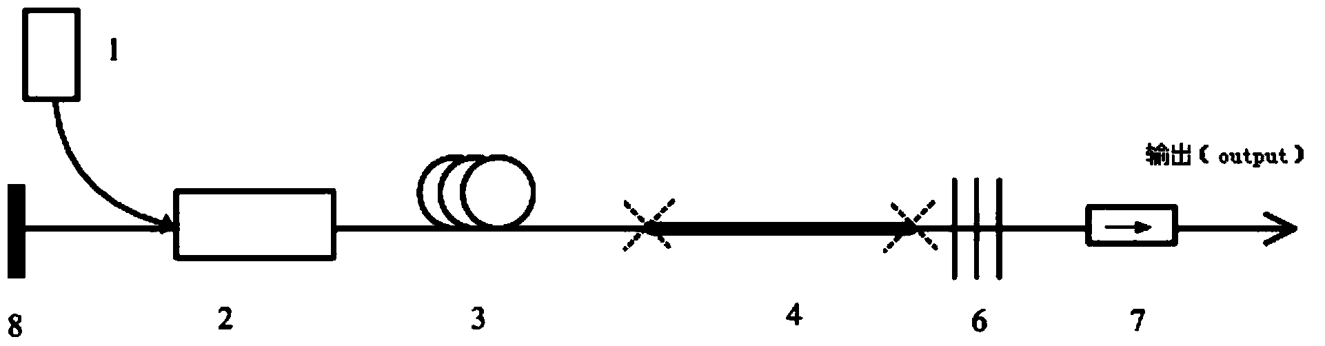
[0028] An all-fiber pulsed laser structure such as figure 2 shown. The only difference from Embodiment 1 is that the reflective fiber Bragg grating 5 is replaced by a total reflection mirror 8 . It is also possible to replace the second reflective fiber Bragg grating 6 with a total reflection mirror.

Embodiment 3

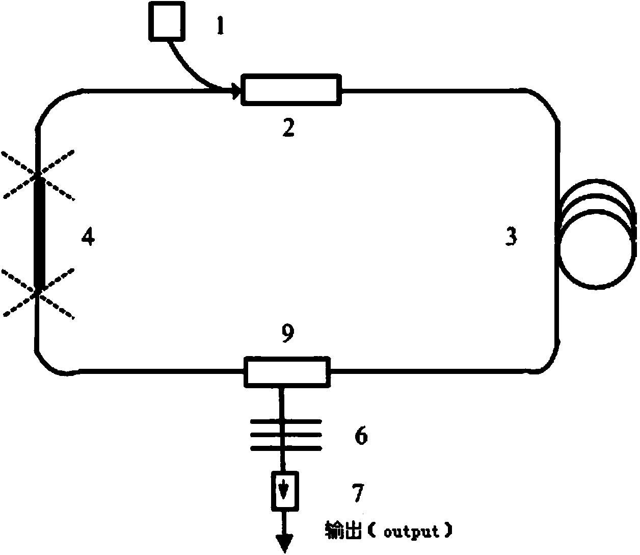
[0030] An all-fiber pulsed laser structure such as image 3 shown. 1 in the figure is the pump source, which can be a semiconductor laser diode with a center wavelength of 976nm; 2 is a fiber beam combiner, which can be a (2+1)×1 pump signal combiner, such as 6 / 125 or 20 / Type 125; 3 and 4 are rare-earth-doped optical fibers, and high-performance ytterbium-doped optical fibers produced by Nufern Company in the United States can be selected; 6 is a reflective fiber Bragg grating, which can be selected from full-reflective or partially reflective gratings, and its reflectivity is R (0

[0031] The pumping light enters through the pump end of the fiber combiner 2, passes through the first gain fiber 3, and enters from the incident end of the circulator 9. The working direction of the circulator is the incident end→common end→exit end, the direction is irreversible, and the common The end is ...


PUM

PropertyMeasurementUnit
Center wavelengthaaaaaaaaaa

Abstract

The invention discloses an all-fiber pulsed laser, and belongs to the field of laser technology and nonlinear optics. The all-fiber pulsed laser includes a pump source (1), an optical combiner (2), a first gain fiber (3), a second gain fiber (4), a first reflective fiber Bragg grating (5), a second reflective fiber Bragg grating (6), an optical isolator (7), a full reflection mirror (8) and a circulator (9), and adopts a structure of linear cavity or annular cavity. By use of the rare earth-doped gain fibers as a laser modulator, with no additional external modulation source and an all-fiber structure, ultrashort pulse laser output of high stability, high power, high energy and high efficiency is achieved. Compared with a semiconductor saturable absorption mirror (SESAM) and graphene (Graphene) modulation Q, mode-locking technology, the all-fiber pulsed laser employs gain fiber for direct pulse modulation, has the advantages of simple design, compact structure and high stability, and is easier to industrialize.

Description

technical field [0001] The invention discloses an all-fiber pulse laser, which belongs to the field of laser technology and nonlinear optics. Background technique [0002] Fiber lasers have the advantages of small size, light weight, high conversion efficiency, and good output beam quality, and have been developed rapidly in recent years. Pulsed lasers with high output power, high beam quality, and high stability are one of the hotspots in the laser field, especially Q-switched and mode-locked fiber lasers, which can generate high-frequency ultrashort pulses and are widely used in optical communication systems, optoelectronics, etc. There are broad prospects in many fields such as sensing, detection and diagnosis, biomedicine, precision micromachining and military affairs. [0003] In the current research on fiber laser Q-switching technology, some people have adopted technologies such as acousto-optic Q-switching and electro-optic Q-switching. Acousto-optic Q-switching us...

Claims


Application Information

Patent Timeline
IPC IPC(8): H01S3/067H01S3/11
Inventor 王璞金东臣
Owner BWT BEIJING
Why Eureka
Try Eureka