Latchable reaming bit

a reaming bit and latching technology, applied in the direction of drilling pipes, cutting machines, borehole/well accessories, etc., can solve the problems of affecting the operation of the reaming bit, the reaming bit could malfunction, and the reaming bit could not be locked,

Active Publication Date: 2008-08-26
BAKER HUGHES INC
View PDF10 Cites 61 Cited by
  • Summary
  • Abstract
  • Description
  • Claims
  • Application Information

AI Technical Summary

Problems solved by technology

However, one problem with the extending arm reamers was that the arms could malfunction and refuse to retract.
This would take a great deal of time and result in extra costs.
The problem with this design was that the bearing on the lower end of the liner was large and prone to failure before the entire hole was made.
This, again, consumed a lot of time and increased costs.
An additional limitation was that such a design required that the reamer bit remain near the liner bottom and did not allow for reaming proximate the pilot bit in the event the pilot bit was required to be operated at a distance downhole from the liner bottom.

Method used


Image

  • Latchable reaming bit
  • Latchable reaming bit

Examples


Embodiment Construction

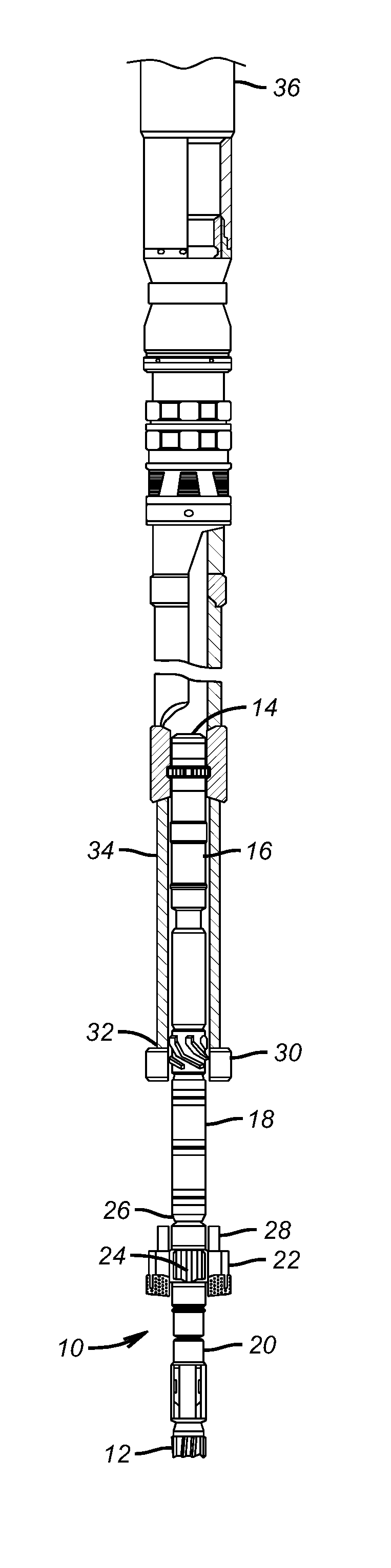
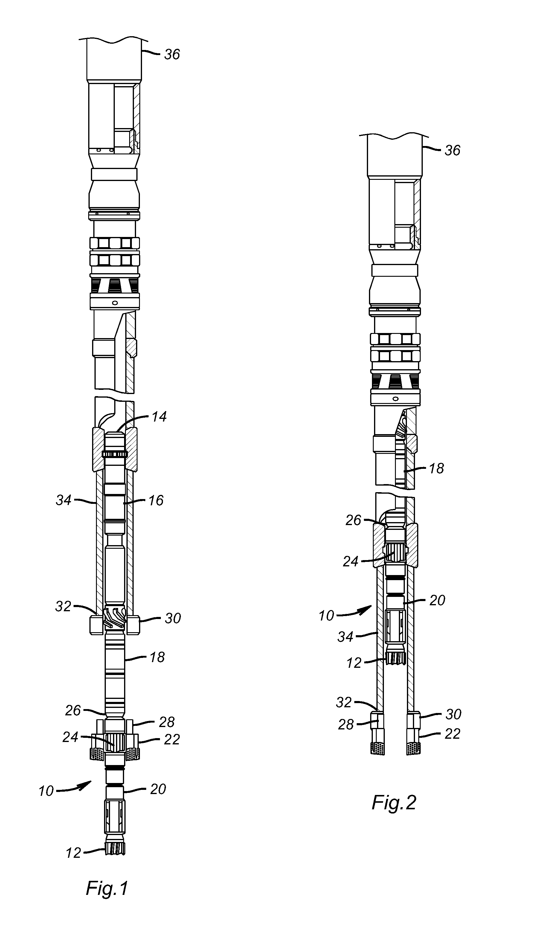
[0009]Referring to FIG. 1 the BHA 10 starts at a lower end with pilot bit 12 and extends to a top end 14. In between are a few known components such as a downhole motor 16 an MWD unit 18 and a steering unit 20 for pilot bit 12. The reamer bit 22 is rotated by the BHA 10 through splines 24. A shoulder 26 on the BHA 10 bears down on the reamer bit 22 when making hole. An internal latch (not shown) keeps the reamer bit 22 from moving down with respect to the BHA as will be explained below. However, the latch may have a lost motion feature so that it is not stressed when making hole in the position shown in FIG. 1.

[0010]The reamer bit 22 has a latch portion 28, which can be either a conventional collet or locking dog configuration or other well-known latching mechanisms that can selectively engage the similar companion latch portion 30 that is located at or near the lower end 32 of liner 34. When the profiles of latch portions 28 and 30 are mated together, the conventional latch (not sh...


PUM


Abstract

A drilling assembly supports a liner for making a wellbore. The BHA comprises a pilot bit and a reamer above it that is larger in diameter than the suspended liner. If the BHA needs to be pulled out, the reamer is brought into contact with the liner and a latch mechanism between the two engages as another latch that had held the reamer bit to the BHA is released. The reamer bit stays with the liner as the BHA is pulled and later reinserted. On the way in the BHA latches to the reamer bit which then unlatches from the liner bottom. Preferably, splines and a shoulder on the BHA are used to drive the reamer bit as opposed to any power being transmitted through the latch between the BHA and the reamer bit. However, the latch mechanism between the BHA and the reamer bit could also provide torque and weight on bit for drilling operations. The process may be repeated.

Description

PRIORITY INFORMATION[0001]This application claims the benefit of U.S. Provisional Application No. 60 / 707,654, filed on Aug. 12, 2005.FIELD OF THE INVENTION[0002]The field of this invention relates to drilling through troublesome zones while advancing a liner and more particularly to techniques for securing a reamer while pulling the bottom hole assembly out for, for example a bit change.BACKGROUND OF THE INVENTION[0003]In the past bottom hole assemblies (BHAs) have been used that included a pilot bit and a reamer. The drill string to which they were attached extended through a liner so that when a troublesome zone was encountered the liner could be used to isolate it. In the course of drilling, the pilot bit or the reamer could wear out or otherwise require removal from the wellbore; for example, to change the type of bit employed. Pulling the BHA through the liner to change the pilot bit for example would not normally be a problem when using a reamer with extendable arms. This was ...

Claims


Application Information

Patent Timeline
Patent Type & Authority Patents(United States)
IPC IPC(8): E21B10/26
CPCE21B10/64E21B7/208E21B10/40
Inventor FORSTNER, INGODURKIN, ANGELAMILLER, TROYMYHRE, MORTEN
Owner BAKER HUGHES INC
Why Eureka
Try Eureka