
Personal recreational vehicle with rotatable seat

a technology of a personal recreational vehicle and a rotatable seat, which is applied in the field of riding propelled vehicles, can solve the problems that the art patent does not provide a rotatable seat on a scooter, and achieve the effects of improving the recreational possibilities and enjoyment of the familiar scooter, easy and safe operation, and increasing the stability of the vehicl

Inactive Publication Date: 2008-08-26
MACKIN STEPHEN +1
View PDF28 Cites 11 Cited by
  • Summary
  • Abstract
  • Description
  • Claims
  • Application Information

AI Technical Summary

Benefits of technology

[0016]A primary object of the present invention is to improve upon the recreational possibilities and enjoyment of the familiar scooter by the addition of a rotatable seat which allows the occupant to spin freely in a chosen direction while the vehicle is in motion. The preferred embodiment of the invention allows the rider to propel the vehicle forward under the rider's own power using feet and legs while standing or while seated.
[0017]Another object of the present invention is to increase the stability of the vehicle by providing a pair of spaced apart wheels on the rear portion of the frame. The rear portion of the invention's footboard is “flared”, in that it is of a significantly wider base as compared to the front portion. The spacing of the rear wheels is such that the vehicle will not readily tip over in response to the centrifugal force applied to the vehicle when the occupant is rotating and also turning the vehicle in a like direction. Additionally, the widened portion of the vehicle's footboard is sufficiently removed from the area in which the rider must place his or her foot on the ground to propel or stop the vehicle, thereby allowing the rider to operate the vehicle without hindrance.
[0018]An additional object of the present invention is to allow the rider to revolve while seated using a number of different techniques and methods. The rider may push against the vehicle's footboard with his feet to set the rotating seat in motion, or the rider may push against the ground to achieve the same rotation. Also, the rider may grasp the steering handles and swivel his weight around the axis of the seat pedestal, rotating freely without his or her legs or feet coming into contact with the vehicle or with the ground. Each of these techniques can be easily and safely performed while still maintaining control over the speed and direction of the vehicle.
[0019]Yet another object of the present invention is to allow the rider to preserve and easily convert between a number of different seated positions while operating the vehicle. Once the rider achieves a desired forward momentum and begins to ride the vehicle while seated, the rotational nature of the seat allows the rider to ride facing any direction, wholly independent from the direction of the vehicle itself. This function of the invention allows many enjoyable and unique ways of riding the vehicle that are not possible or safe utilizing existing forms of scooters or other seated vehicles.
[0020]In brief, the recreational personal vehicle of the present invention comprises a frame with a foot support or footboard and rear wheel support for two rear wheels spaced apart for stability. A front steering column, pivotally attached to the frame, may have a single wheel or spaced apart double wheels for greater stability for a four wheel vehicle. A seat support pedestal extends upwardly from the frame near the back to support a rotatable seat which enables many fun and challenging maneuvers while riding.

Problems solved by technology

While some recreational vehicles provide seats, the prior art patents do not provide a rotatable seat on a scooter to enhance the fin value and potential activities and maneuvers possible with a rotatable seat.

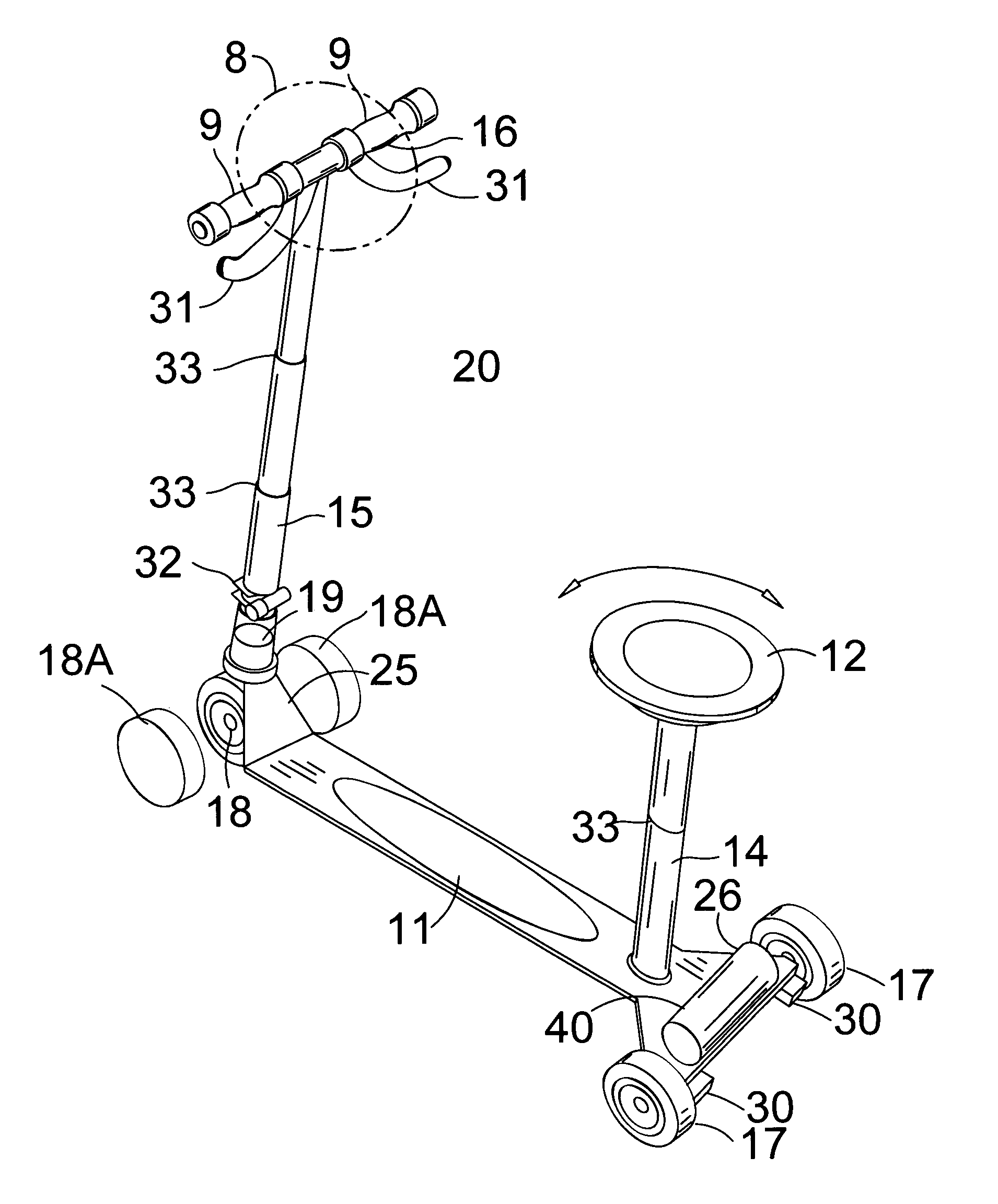
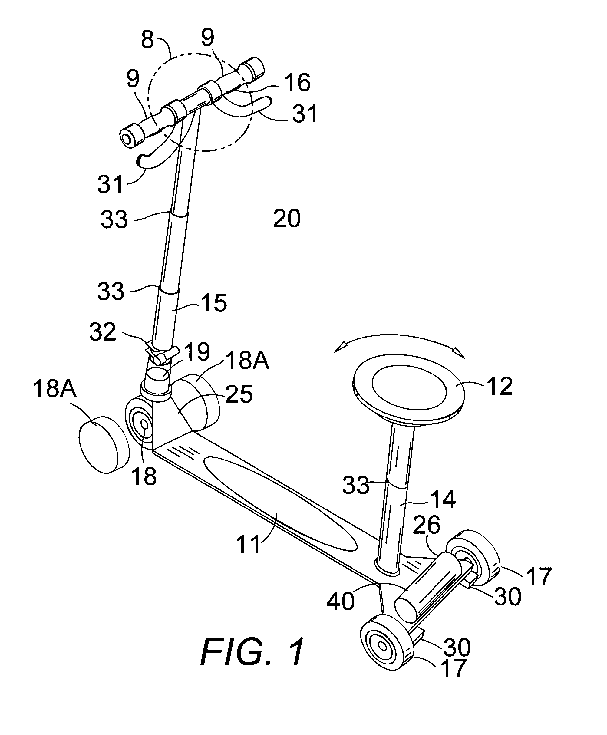
Method used


Image

  • Personal recreational vehicle with rotatable seat
  • Personal recreational vehicle with rotatable seat
  • Personal recreational vehicle with rotatable seat

Examples


Embodiment Construction

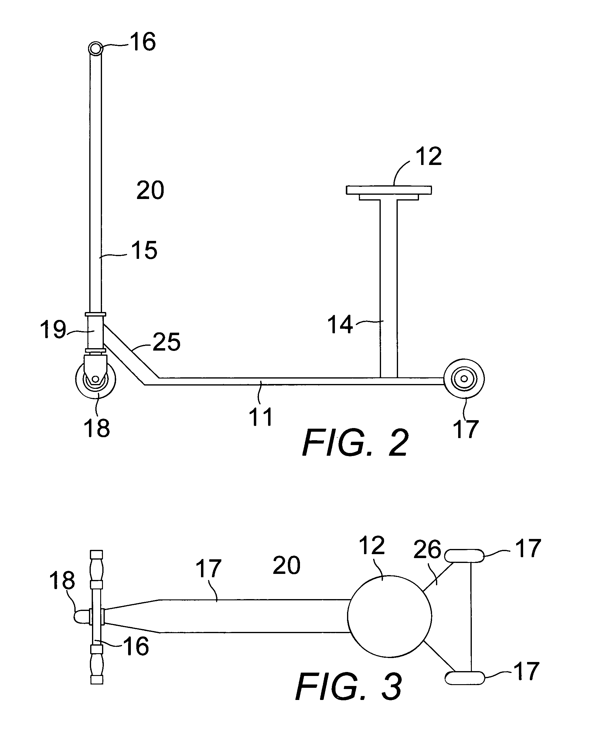
[0029]In FIGS. 1-7 a recreational personal vehicle 20 and 20A comprises a frame 11 and 11A supporting a front steering column 15 and front wheel 18, a pair of rear wheels 17 and a rotatable seat 12 and seat support pedestal 14 and 14A.

[0030]In FIGS. 1-3, the frame comprises an elongated foot support portion 11 comprising an elongated flat metal plate for receiving the feet of a rider and a rear wheel support portion 26 comprising a rigid extension of the footboard portion extending laterally from both sides of a rear end of the frame. The rear wheel support portion 26 is shaped like a truncated isosceles triangle with the truncated top of the triangle adjacent to the footboard portion 11 and the two sides of the triangle angled back and out from the footboard portion to a back end of the frame forming a base of the triangle perpendicular to a longitudinal centerline of the frame. The pair of rear wheels 17 are each attached to an outer end of the rear wheel support portion 26 spaced...


PUM


Abstract

A frame has a foot support and rear wheel support for two rear wheels spaced apart for stability. A front steering column, pivotally attached to the frame, may have a single wheel or spaced apart double wheels for greater stability for a four wheel vehicle. A seat support pedestal extends upwardly from the frame near the back to support a rotatable seat.

Description

CLAIM OF PROVISIONAL APPLICATION RIGHTS [0001]This application claims the benefit of U.S. Provisional Patent Application No. 60 / 577,964, filed on Jun. 08, 2004.BACKGROUND OF THE INVENTION [0002]1. Field of the Invention[0003]The present invention relates to rider propelled vehicles and particularly to a scooter having a front wheel attached to a steering column, a deck, two rear wheels for stability and a rotatable seat on a seat support extending upwardly from the deck.[0004]2. Description of the Prior Art[0005]Scooters have long been a favored mode of transportation for children. Most scooters are made with a front steerable wheel and a rear wheel. Three wheel scooters include a steerable front wheel and two spaced apart rear wheels, together with a support platform located between the front and rear wheels. This platform is mounted at the same level or is depressed below the level of the wheel axles to provide a low center of gravity. The handle bars for steering the front wheel ...

Claims


Application Information

Patent Timeline
Patent Type & Authority Patents(United States)
IPC IPC(8): B62M1/00B62J1/00B62K3/00
CPCB62K3/002B62J1/00
Inventor MACKIN, STEPHENNEWTON, ERNEST
Owner MACKIN STEPHEN
Learn More