
Handheld pipette

Inactive Publication Date: 2008-08-26
VISTABLAB TECH LLC
View PDF90 Cites 14 Cited by
  • Summary
  • Abstract
  • Description
  • Claims
  • Application Information

AI Technical Summary

Benefits of technology

[0013]An adapter may be provided which is selectively mountable to the body portion, the adapter adjusting the size of the body portion to better fit operator hand size. Padding may also be provided on at least a portion of the body portion. Por

Problems solved by technology

Since an operator using such a pipette may do hundreds of aspirations / dispensings in a single day, repetitive stress injuries are a common problem for such operators.
Many complain of wrist and shoulder injuries caused by extended periods of pipetting using traditional axial pipette designs and forearm strain is also a common complaint.
Another potential source of injury is the fact that, for most operations, the user's wrist / hand must be rotated while performing the operation rather than being held in its natural or neutral position which is generally approximately 45° to both the horizontal and vertical.
Another problem with existing designs is that, with the tip being an extension of the cylindrical pipette, the pipette is relatively long, making it difficult to maneuver and use under a laboratory fume hood and forcing the operator to hold the pipette above the receptacle being aspirated from or dispensed into.
This places stress on the muscles and joints of the shoulder, which, over time, results in fatigue and can ultimately lead to injury.
The position of the nozzle and tip away from the operator's fingers also reduces the operator's “feel” of the tip and make it more difficult for the operator to control the tip, adding further to the fatigue and strain of performing pipetting operations.
Another ergonomic problem for pipettes is that operator discomfort and injury can result from points on a pipette which cause high contact pressure on the operator's fingers, thumb or other portions of the operator's hand.
Few, if any, existing pipettes satisfy this criteria.
Deeper immersion can result in inaccurate aspiration of the fluid and can cause other potential problems.
While some existing pipettes provide a limited number of these capabilities, a pipette design providing all, or at least most, of these capabilities does not currently exist.

Method used


Image

  • Handheld pipette
  • Handheld pipette
  • Handheld pipette

Examples


Embodiment Construction

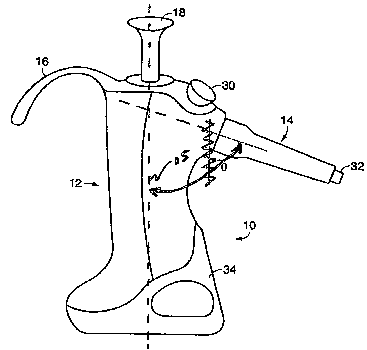
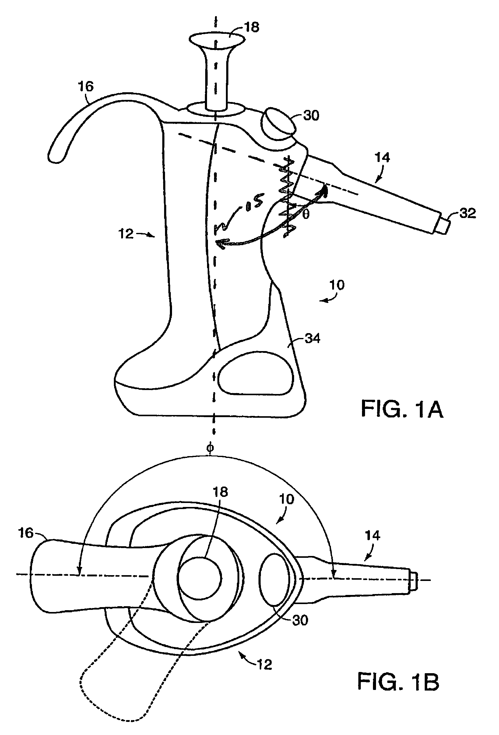
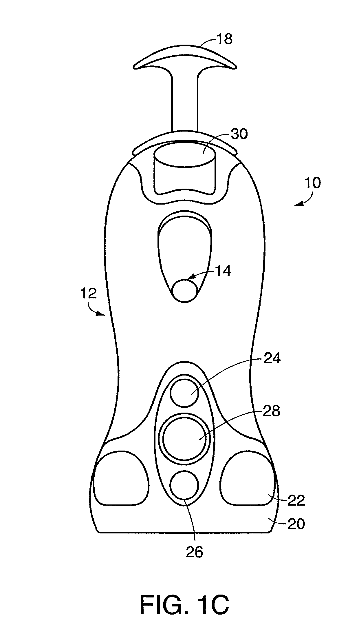
[0026]Referring to FIGS. 1A-1C, it is seen that the pipette 10 of this invention includes a body portion 12 and a nozzle portion 14. Nozzle portion 14 extends from a point near the top of body portion 12 and is at an angle θ to the center line 15 of the body portion. The angle θ is roughly the angle required for the nozzle portion 14 to be at a good working angle as shown in FIGS. 2, and 7 (i.e. roughly 35° from vertical), when the wrist, elbow and shoulder of an operator are all in substantially the neutral position previously discussed. This angle θ is typically approximately 60° to 80°, the angle θ being approximately 70° for an illustrative embodiment of the invention.

[0027]The neutral position for the wrist is approximately 45° and ergonomists recommend not rotating the wrist more than plus or minus 45° from the neutral. While as seen in FIG. 6A, the wrist angle for a standard axial pipette is approximately 135°, as is seen from FIGS. 2 and 7A, the wrist angle for the pipette o...


PUM


Abstract

This invention provides a hand held pipette which is ergonomically designed to reduce user fatigue and injury. The pipette preferably includes a nozzle extending downward at a selected angle from a point near the top of a base portion of the pipette, the base portion being grasped by the operator's hand, and may also include a hook extending from a second point near the top of the body portion which is angularly spaced from the first point, which hook extends over a portion of a user's hand to support the pipette thereon. The pipette is also designed to permits operation with the user's wrist and arm in a neutral position and minimizes local pressure points on the operator's hand.

Description

RELATED APPLICATIONS[0001]This Application claims priority from provisional application Ser. No. 06 / 214,143, filed Jun. 26, 2000.FIELD OF THE INVENTION[0002]This invention relates to handheld pipettes, and more particularly to an improved, more ergonomic such pipette.BACKGROUND[0003]Handheld pipettes are utilized to aspirate one or more fluids from a first receptacle containing such fluids, generally a precise quantity of such fluid, and to dispense the fluid to a second receptacle where the fluid may be analyzed or otherwise tested. To prevent interaction between successive samples, while minimizing cleaning / sterilization requirements, disposable tips are typically mounted to the pipette nozzles. Since an operator using such a pipette may do hundreds of aspirations / dispensings in a single day, repetitive stress injuries are a common problem for such operators. Many complain of wrist and shoulder injuries caused by extended periods of pipetting using traditional axial pipette design...

Claims


Application Information

Patent Timeline
IPC IPC(8): B01L3/02B65D5/72G01N1/00
CPCB01L3/0217B01L3/0286B01L2300/027B01L2200/087
Inventor SCORDATO, RICHARD E.PAGE, LOU ANNCOSTELLO, KEVINSCHIEFFER, SONYANATSUME, GARY SHIGERU
Owner VISTABLAB TECH LLC
Features
  • Generate Ideas
  • Intellectual Property
  • Life Sciences
  • Materials
  • Tech Scout
  • Unparalleled Data Quality
  • Higher Quality Content
  • 60% Fewer Hallucinations
Learn More