Connector for steel catenary risers

Active Publication Date: 2018-04-19
SINGLE BUOY MOORINGS INC
4 Cites 0 Cited by

AI-Extracted Technical Summary

Problems solved by technology

For small diameter connectors, the problem causing tooth spacing misalignment mentioned in subparagraph a, above, is a result of strain limits of the connector requiring very small teeth with limited engagement and Poisson's effect.
When these teeth are forced over one another, the inner pin member goes into compression, which causes a lengthening of the connector pin and teeth.
The opposite occurs for the box as ...

Benefits of technology

[0016]The present invention relates to a coaxial parallel-thread connector that is designed to be made-up by forcing the coaxial threads over each other until a position is reached where the tooth geometry matches and they engage. To minimize the high stresses that may occur as the teeth are forced over each other, a system of using a pressurized fluid between the teeth to m...

Abstract

Methods that may be employed to help to equalize the length of the teeth on a pin-and-box SCR connector during make-up include locating the make-up groove on the box at the far box end away from the pipe end. This causes the make-up force to tension and stretch the box to make it longer. Additionally or alternatively placing grease or other fluid in the nib groove creates a resistance force to nib entry. The grease or fluid exits through a nib vent port in the box while creating a resistance that compresses the pin and stretches the box causing the tooth spacing of the pin and the box to be similar. Providing a ring groove at both ends of the box allows a tensioning device to be used to tension the box causing box elongation, which equalizes the tooth length of pin and box members during connector make up.

Application Domain

Pipe laying and repairDrilling rods +3

Technology Topic

Tooth lengthCatenary +2

Image

  • Connector for steel catenary risers
  • Connector for steel catenary risers
  • Connector for steel catenary risers

Examples

  • Experimental program(1)

Example

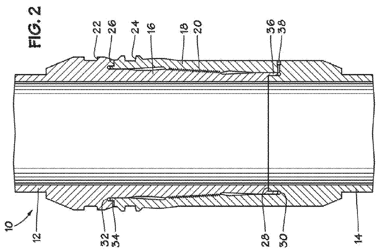
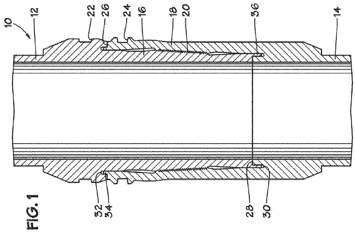
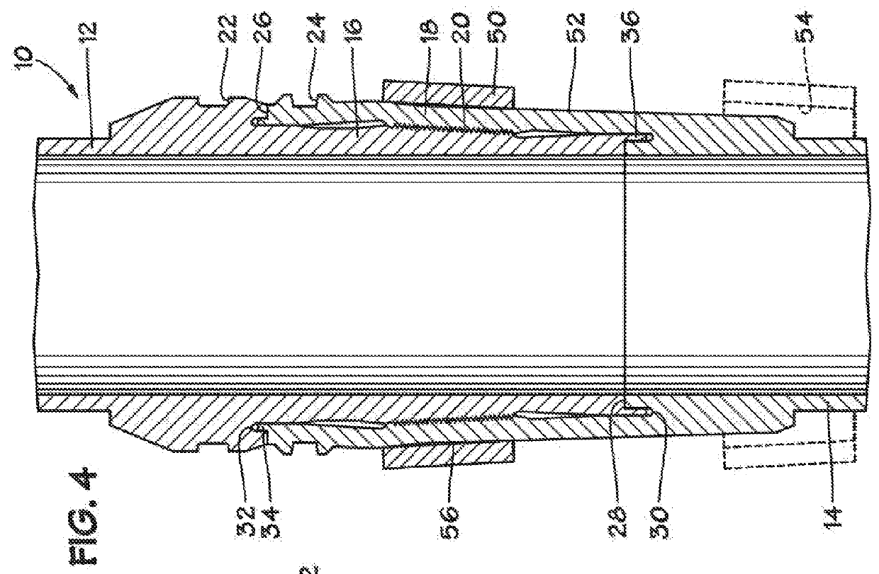
[0029]The invention may best be understood by reference to the drawing figures wherein the following reference numbers are used: [0030] 10 SCR connector [0031] 12 first pipe section [0032] 14 second pipe section [0033] 16 pin member [0034] 18 box member [0035] 20 grooved portion [0036] 22 pin clamping groove [0037] 24 box clamping groove [0038] 26 first shoulder abutment [0039] 28 second shoulder abutment [0040] 30 box annular groove [0041] 32 pin annular groove [0042] 34 box axially extending tongue [0043] 36 pin axially extending tongue [0044] 38 radial duct [0045] 40 pipe-end box-stretching groove [0046] 42 stretching tool [0047] 50 external sleeve [0048] 52 tapered outer surface on box [0049] 54 tapered inner surface on sleeve [0050] 56 interference fit [0051] 58 annular spacer [0052] 60 external sleeve [0053] 62 radially extended pin clamping groove [0054] 64 sleeve clamping groove [0055] 66 tapered section [0056] 68 OD shoulder interface [0057] 70 radial duct [0058] 72 pipe-end box clamping groove [0059] 71 sleeve installation tool
[0060]A pipe connector of the prior art is described in U.S. Pat. No. 5,954,374 to Gallagher, et al. The pipe connector includes a tubular pin member having a generally frusto-conical outer peripheral surface and a tubular box member having a generally frusto-conical inner peripheral surface corresponding to the frusto-conical outer peripheral surface of the pin member and overlies the frusto-conical surface of the pin member when the members are fully engaged together. The members include with inter-engageable annular projections and grooves on the peripheral surfaces for axially locking the members together when they are fully engaged, the projections and grooves being spaced apart along the surfaces. Means are provided for supplying hydraulic fluid under pressure between the overlying parts of the surfaces of the members when fully engaged to expand the box member and/or contract the pin member to bring the projections out of engagement with the corresponding grooves and permit the members to be disengaged.
[0061]During make-up of the connection, after the members have been telescoped together to their initial positions, they may be fully engaged by simply applying an axial force to the members. Engagement may be assisted by the application of pressurized hydraulic fluid to the overlapped portions of the surfaces, and the members may be disengaged in the same way, the pressurized fluid expanding the box and/or contracting the pin to permit engagement and disengagement, and lubricating the crest surfaces of the projections and the surfaces between the grooves to facilitate the sliding of these surfaces over one another during make-up of the connection. For this purpose, the box member is provided with a radial duct for connection to a source of pressurized hydraulic fluid. The duct opens inwardly of the box into the region of the frusto-conical surface of the box which is provided with the projections or grooves. To ensure that the hydraulic fluid is able to flow along the full length of the overlapped portions of the surfaces of the members having radially extending the grooves, axial grooves may be provided, at least one in the pin member and the other in the box member, with the duct opening into the groove in the box member.
[0062]To help overcome Poisson-effect misalignment, applying more compression to the pin during makeup or tension to the box during make-up brings the teeth into closer alignment. Because the pin is inside the box, it is difficult to directly apply a force to it. The box, however, is accessible and one may physically stretch it to neutralize the Poisson effect. Currently, the make-up of these connectors is accomplished by pushing the connector together from ring grooves at the pipe end of the pin and at the pipe end of the box. The typical arrangement of these ring grooves is depicted in U.S. Pat. No. 5,954,374 to Gallagher et al. In such an arrangement, when the connector is forced together, the axial force used to effect the engagement causes compression in both the pin and box. The compression of the box worsens the tooth misalignment inasmuch as it further compresses the box, shortening the length of the teeth.
[0063]There are several methods that may be employed to help equalize the length of the teeth on the pin and box during make-up: [0064] i. Locating the make-up groove on the box at the far box end away from the pipe end. This will cause the make-up force to tension and stretch the box to make it longer. Such a make-up groove on the box end of a connector is illustrated in FIG. 1. [0065] ii. Using the box make-up groove as in subparagraph i, above, placing grease or other viscous fluid in the ID nib groove to create a resistance force to nib entry. The grease or other viscous fluid exits through a nib vent port in the box while creating a resistance that compresses the pin and stretches the box causing the tooth spacing of the pin and the box to be similar. This embodiment is illustrated in FIG. 2 which may optionally comprise a valve or variable orifice on the vent port. [0066] iii. Providing a ring groove at both ends of the box such that a tensioning device may be used to tension the box causing box elongation, which equalizes the tooth length of the pin and the box while the connector is made up. This embodiment is illustrated in FIG. 3.
[0067]Referring first to FIG. 1, SCR connector 10 comprises first pipe section 12 having pin member 16 on one end and second pipe section 14 having box member 18 on one end. A grooved portion 20 on each of the pin and box members has teeth (projections) with grooves (depressions) between them that engage with corresponding teeth and grooves on the opposite member to lock the pin and box members together when the joint is fully made up. In an embodiment, the teeth are coaxial, parallel threads and portion 20 is tapered.
[0068]In the embodiments illustrated in FIGS. 1 and 2, pin member 16 is equipped with pin clamping groove 22 conventionally located near the pipe end of the pin member. However, box clamping groove 24 is unconventionally positioned at the open end of box member 18 so that a tensile force applied by a joint make-up tool between pin clamping groove 22 and box clamping groove 24 will tend to axially stretch box member 18.
[0069]When the joint is fully made up, the two joint ends axially abut at first shoulder abutment 26 and second shoulder abutment 28. To ensure a fluid-tight seal, box annular groove 30 and pin annular groove 32 may be provided together with corresponding box axially extending tongue (or projection) 34 and pin axially extending tongue (or projection) 36 which may have interference fits with grooves 30 and 32, respectively, as is more fully described in U.S. Pub. No. 2014/0265320.
[0070]As illustrated in FIG. 2, box member annular groove 30 may be provided with radial port 38 which is in fluid communication with an exterior surface of box member 18. During joint make up, grease or other fluid (which may be a viscous fluid) may be placed in groove 30. When axially extending projection 36 on pin member 16 is inserted in groove 30 the fluid provides resistance thereby compressing pin member 16. Duct 38 provides a controlled rate of fluid discharge from groove 30, preventing a hydraulic lock condition that might make full joint make up impossible. In certain embodiments, radial duct 38 may be provided with a valve, an orifice, or a selectable orifice to provide a certain desired rate of fluid discharge during joint make up.
[0071]Referring now to FIGS. 3 and 3A, another embodiment is illustrated wherein pin member 18 is additionally provided with pipe-end box-stretching groove 40. Stretching tool 42 engages open-end box-stretching 24 and pipe-end box-stretching groove 40 to apply a separating force between grooves 24 and 40 (as indicated by the arrows in FIG. 3) thereby stretching box member 18 during joint make up.
[0072]Another method according to the invention for improving tooth engagement and managing the stresses of these small diameter connector teeth is to add steel to the box outer diameter after make-up. A problem experienced with these small connectors when subject to large tensile or bending loads is that the hoop forces generated by the flank angle of the teeth create radial forces that compress the pin and expand the box. These radial forces may cause a wider separation between the pin and the box members thus reducing the tooth engagement. This reduction in engagement increases the tooth stress and may cause the teeth to slip and disengage.
[0073]One possible solution to this problem might be increasing the wall thickness of the pin and box members. However, such increased thickness would make it more difficult to expand and contract the box and pin and would increase the tooth loading during make-up. Inasmuch as the make-up tooth loading may already be approaching a limit, increasing the wall thicknesses is not a viable option, as it would require much higher pressures to make up the connector. These pressures would not be safe to use in the field during assembly. Higher strength steel materials also provide no help inasmuch as the material stiffness remains the same, resulting in the same relative pin-to-box deformations.
[0074]A positive method for ensuring good tooth engagement both in make-up and during connector operation is reducing the box thickness and adding additional steel to the outer diameter of the box once the teeth have been made up. This method helps in several ways, as it first makes the box member easier to expand and to stretch during make-up using one of the three methods described above. This reduction in box member thickness allows a reduction in the make-up pressure, as it is easier to expand and also to stretch with the make-up force of the methods described above. One may also use a thinner, higher strength steel for the box member that has the capability to expand further in hoop with a lower pressure.
[0075]Once the connector has been made-up, a prepositioned outer shell (or sleeve) with a conical interface may be slipped into place on the thinner box. This extra steel may have a tight or compressive fit on the box so as to stiffen the box sufficiently to minimize any potential for expansion causing a problem with lack of tooth engagement. The extra steel may also be sized and configured to compress the box onto the pin thus increasing tooth engagement. This embodiment is illustrated in FIG. 4 wherein external sleeve 50 is shown installed on tapered outer surface 52 on box member 18. Tapered inner surface 54 on sleeve 50 provides an interference fit 56 with outer surface 52 when fully seated radially opposite grooved portion 20 of connector 10. As shown in dashed lines in FIG. 4, sleeve 50 may be pre-positioned on box member 18 prior to joint make up.
[0076]In certain embodiments, the extra steel placed on the box is not prepositioned on the connector. Rather, it comprises a separate shell fastened onto the box using means that secure it in intimate contact or compression. This member may also be wound or affixed onto the box in any way that results in a significant hoop stiffening of the box.
[0077]As disclosed in U.S. Pub. No. 2014/0265320, in a pipe joint where two pipe sections have engaged pin and box members, the joint ends are substantially sealed to each other by a sealing surface on one pipe section that substantially abuts a sealing surface on the other pipe section. In one joint, a ring-shaped cutout may formed in a first pipe section and a ring-shaped spacer (58 in FIGS. 5, 6A and 6B) is located in the cutout. The spacer may be chosen from several that have slightly different lengths so the spacer end contacts the corresponding sealing surface. The joint can be pressurized by a fluid (liquid or gas) directed through a port (70 in FIG. 5), which radially compresses the pin member and which radially expands the box member, thereby easing the threads over one another.
[0078]Referring now to FIG. 5, an external sleeve 60 may be installed on the pin and box connector assembly with a tapered section that preloads the box connector radially and also axially restrains the pin connector. The sleeve may be axially located on the pin using a press fit or helically threaded onto the external surface of the pin below the outside diameter (OD) shoulder. The external sleeve may also have a surface projection that positively engages a groove on the pin connector side during make-up.
[0079]The external sleeve 60 may be equipped with clamping groove 64 similar to groove 62 on pin connector 18. The pin clamping groove 62 may be moved out radially to accommodate this.
[0080]The external sleeve design may have surface features (by either material addition or removal) designed to seal against the pin and box connector and keep seawater away from their OD interface 68. Elastomeric O-ring type seals may also be used as part of the design to keep seawater out of the OD shoulder interface.
[0081]The external sleeve may be installed over the box connector and axially restrained on the pin connector providing resistance to load and relative axial displacement between the pin and the box and improvement of the OD shoulder preloads capacity of the connector as well as the tooth engagement between the pin and box connector.
[0082]The external sleeve may be installed and disassembled with the same tooling as required for assembling the pin and box connectors. No additional tooling is required. The assembly sequence is illustrated sequentially in FIGS. 6A and 6B.
[0083]In an embodiment, the sleeve is threaded onto the box. In yet another embodiment, the sleeve is split and clamped onto the box.
[0084]In certain embodiments, the sleeve compresses the box onto the pin thereby providing greater tooth engagement in both loaded and unloaded conditions.
[0085]The foregoing presents particular embodiments of a system embodying the invention. Those skilled in the art will be able to devise alternatives and variations which, even if not explicitly disclosed herein, embody those principles and are thus within the scope of the invention. Although particular embodiments of the present invention have been shown and described, they are not intended to limit what this patent covers. One skilled in the art will understand that various changes and modifications may be made without departing from the scope of the present invention as literally and equivalently covered by the following claims.

PUM

no PUM

Description & Claims & Application Information

We can also present the details of the Description, Claims and Application information to help users get a comprehensive understanding of the technical details of the patent, such as background art, summary of invention, brief description of drawings, description of embodiments, and other original content. On the other hand, users can also determine the specific scope of protection of the technology through the list of claims; as well as understand the changes in the life cycle of the technology with the presentation of the patent timeline. Login to view more.

Similar technology patents

Rolling bearing

InactiveCN101120180Areduce contact stressInhibit wear
Owner:NTN CORP

Mechanical friction type stepless speed change device

InactiveCN1442623Areduce contact stressextend your life
Owner:北京中资燕京汽车有限公司

Clutch of electric power unmanned aerial vehicle

InactiveCN105370761Agood impact resistanceReduce contact stress
Owner:STATE GRID SHANDONG ELECTRIC POWER +2

Contact backstop of logarithmic spiral profile wedge blocks

InactiveCN102730373AStable working performancereduce contact stress
Owner:UNIV OF SCI & TECH LIAONING

Handheld pipette

InactiveUS7416704B2minimize contact pressure
Owner:VISTABLAB TECH LLC

Anti-loose internally threaded fastener

InactiveCN103216513AImprove mechanical propertiesreduce contact stress
Owner:吉林市翔达电动车厂

Classification and recommendation of technical efficacy words

  • minimize contact pressure

Handheld pipette

InactiveUS7416704B2minimize contact pressure
Owner:VISTABLAB TECH LLC
Why Eureka
Try Eureka