Apparatus and method for monitoring tap positions of load tap changer

Active Publication Date: 2008-08-26
ADVANCED POWER TECH
View PDF7 Cites 37 Cited by
  • Summary
  • Abstract
  • Description
  • Claims
  • Application Information

AI Technical Summary

Problems solved by technology

A problem exists in ascertaining which tap is being contacted because the number of shaft rotations needed to go from a first tap to a second tap may be different than those needed to go form the second tap to a third tap, and so on.

Method used


Image

  • Apparatus and method for monitoring tap positions of load tap changer
  • Apparatus and method for monitoring tap positions of load tap changer
  • Apparatus and method for monitoring tap positions of load tap changer

Examples


Embodiment Construction

[0022]Note that certain aspects of this invention are also described in co-pending application titled SENSING LOAD TAP CHANGER (LTC) CONDITIONS bearing Ser. No. 11 / 520,542 and filed on the same day as this application and the teachings of which are incorporated herein by reference.

[0023]The invention will now be described with reference to FIGS. 3 through 8.

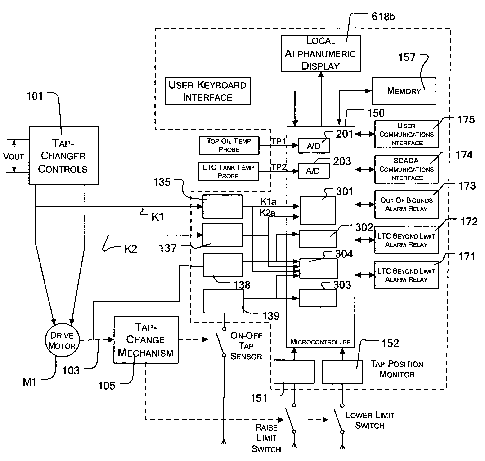
[0024]As shown in FIG. 3, the main power transformer, XFR, the LTC windings 100a and the potential sensing transformer PT10 may be located in a main tank 401. The LTC taps 100b (taps T0-TM connected to windings 100a) may be located in a different, adjacent, LTC tank 403. The tap change controller and the motor M1, as well as some of the system electronics, may be located in an adjacent control cabinet 405. The tanks 401 and 403 may be filled with a liquid (e.g., oil) for distributing the heat generated by their respective components. A main tank temperature probe, TP1, (also called the top oil temperature probe) may be used to me...


PUM


Abstract

A load tap changer (LTC) having a plurality of windings is coupled to one of the primary and secondary windings of a power transformer in order to regulate the output voltage of the power transformer. The LTC includes a plurality of taps physically and electrically connected to the LTC windings and the transformer's output voltage is increased / decreased by moving along the taps a contacting element whose movement is controlled by a rotating shaft driven by a motor. The tap being contacted is determined by sensing the direction and number of shaft rotations and by checking the number of shaft rotations specified to go from a tap to the next tap being contacted. The time for a full rotation of the shaft is also measured. Also, the temperature of the tanks containing the LTC taps and the power transformer is measured for each tap position.

Description

[0001]This invention claims priority from provisional application Ser. No. 60 / 717,000 for Load Tap Changer Position Monitoring Method filed Sep. 14, 2005 and application Ser. No. 60 / 716,996 titled Load Tap Changer Condition Monitoring Method filed Sep. 14, 2005.BACKGROUND OF THE INVENTION[0002]This invention relates to apparatus and method for monitoring and displaying the tap positions of a load tap changer (LTC).[0003]Load Tap Changers (LTCs) are used in electric power systems to regulate the voltage distributed from substations and along the power lines. An LTC, as used and defined herein and in the appended claims, may be connected in the primary circuit of a power transformer, XFR, as shown in FIG. 1, or in the secondary circuit as shown in FIG. 2. FIG. 1, is a highly simplified version of a prior art system illustrating use of one type of LTC connected in the primary circuit of a power transformer (XFR). In FIG. 1, there is shown the primary (P1) of a power transformer (XFR) t...

Claims


Application Information

Patent Timeline
Patent Type & Authority Patents(United States)
IPC IPC(8): G05F1/147
CPCG05F1/147
Inventor HOFFMAN, GARY R.TENNILLE, THOMAS C.
Owner ADVANCED POWER TECH
Why Eureka
Try Eureka