Dynamic pluggable user interface layout

a plug-in user interface and layout technology, applied in the field of display formatting, can solve the problems of burdening the programmer, limiting the programming technique of the typical graphic user interface (gui) to statically and/or explicitly controlling the bounds, and affecting the implementation of scenarios

Active Publication Date: 2008-08-26
MICROSOFT TECH LICENSING LLC
View PDF11 Cites 53 Cited by
  • Summary
  • Abstract
  • Description
  • Claims
  • Application Information

AI Technical Summary

Problems solved by technology

Typical graphic user interface (GUI) programming techniques are limited to statically and / or explicitly controlling the bounds of a display.
This adversely affects the implementation of scenarios in which the control bounds are to be dynamic, or at least appear dynamic to the user, because of the extensive amount of code required to manage this layout.
This code is often burdensome to the programmer because of its complexity and because writing this code can be time consuming.
This type of code can also adversely affect the user because the user may have to wait too long for the code to perform its function (i.e., to update the layout), thus negating the dynamic characteristic the code was designed to exhibit.
These problems are exacerbated in situations where the potential exists for changes to the layout of one portion of a display to affect the layout of other portions of the display.
These problems are also evident in situations in which an extensible model is desired.
Additionally, controls that are written to support dynamic adjustment of bounds are often error prone, and inefficient.
An example of a scenario in which this type of code presents severe disadvantages is the increasingly common use of browser like interfaces to dynamically control the layout of a display.
Existing techniques for enabling these dynamic changes suffer from the above-mentioned disadvantages of being error-prone, inefficient, and being difficult to implement.

Method used


Image

  • Dynamic pluggable user interface layout
  • Dynamic pluggable user interface layout
  • Dynamic pluggable user interface layout

Examples


Embodiment Construction

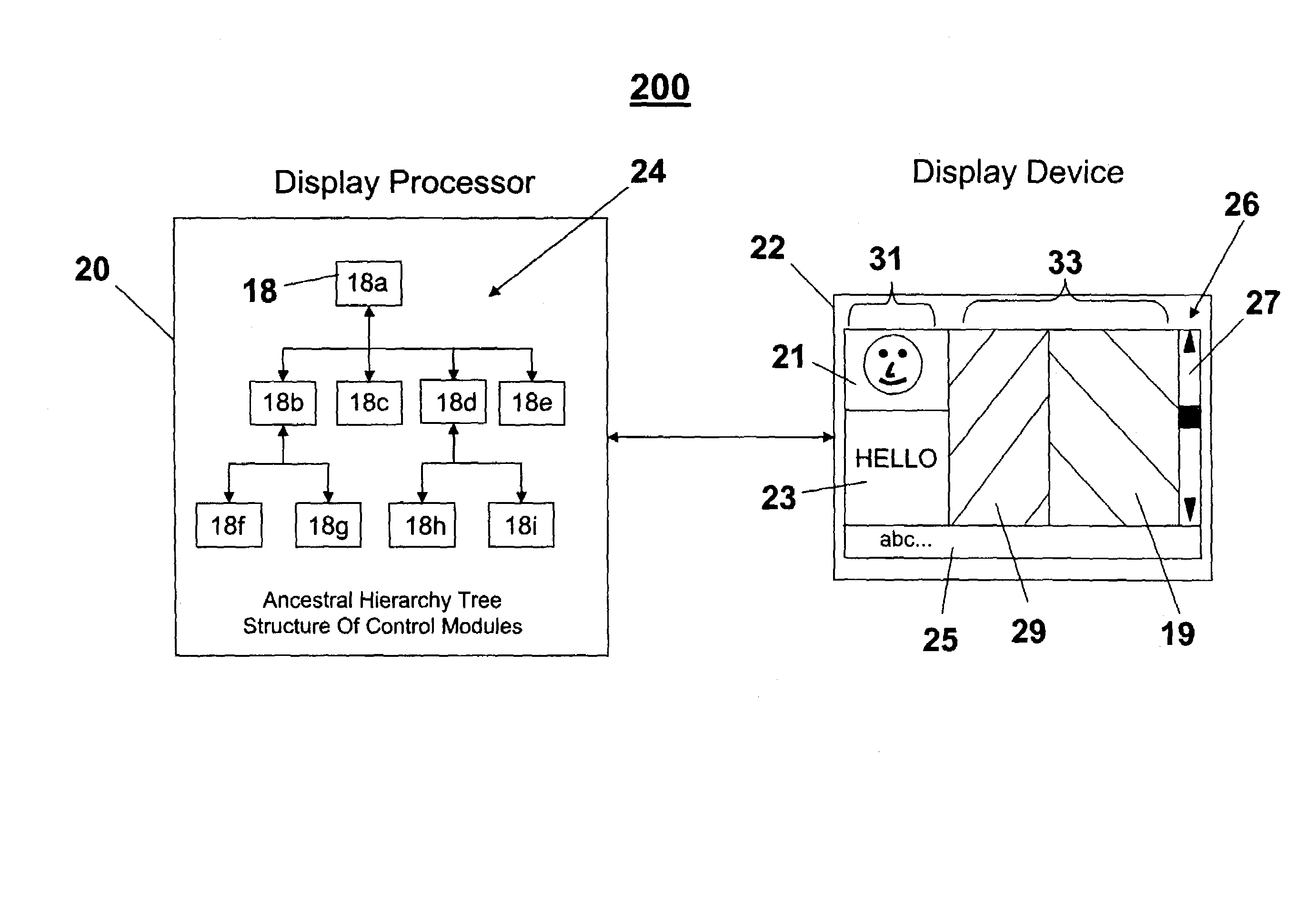
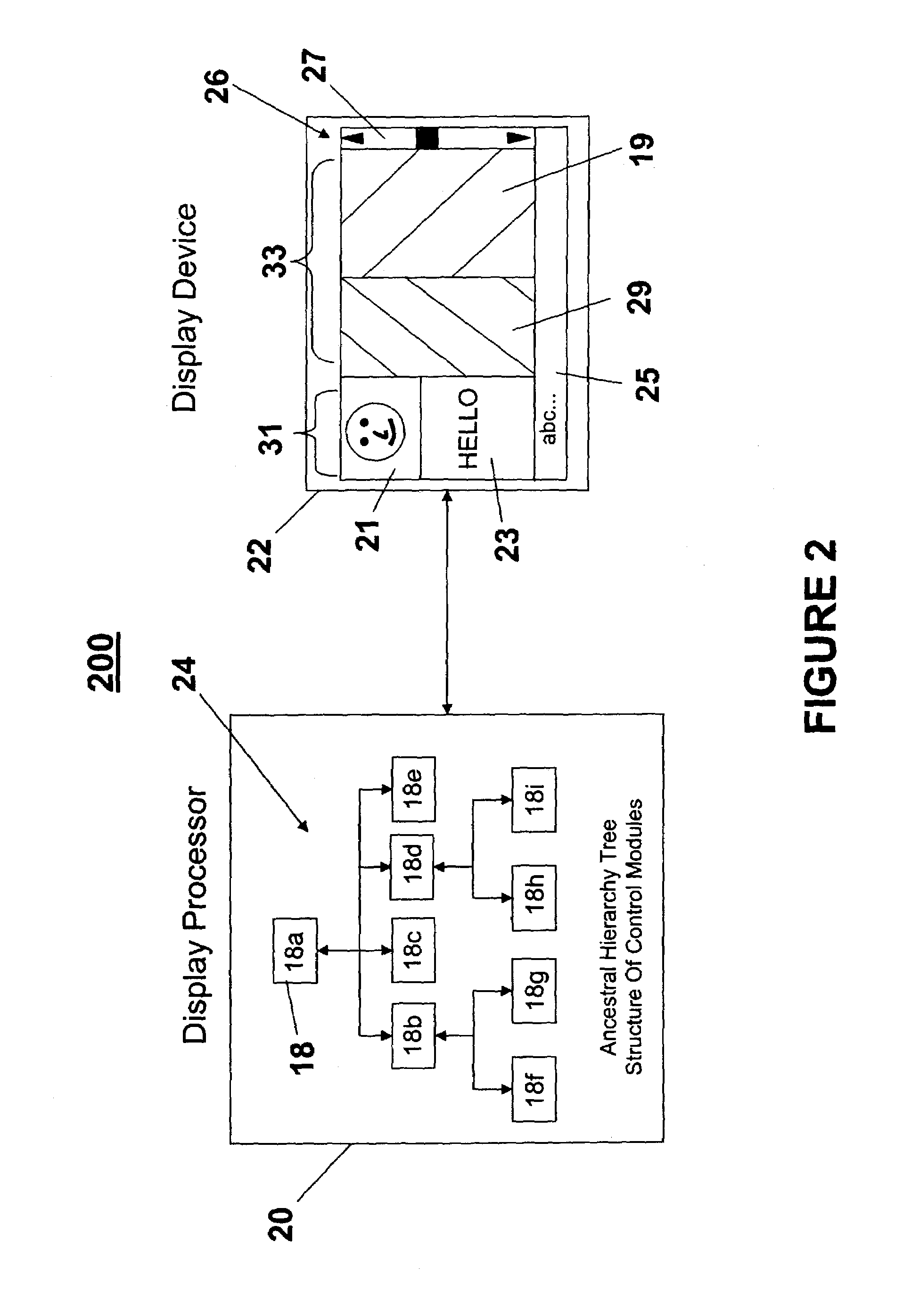
[0014]A system and method for dynamically laying out a display utilizing pluggable control modules in accordance with an embodiment of the present invention provides a user, such as a designer of a web page, the ability to individually control the layout (e.g., boundaries, dimensions) of display elements (e.g., separate regions) of the display without requiring all the display elements of the display to be reformatted when one portion of the layout changes. Each control module is dedicated to controlling the format of a particular display element. The control modules are organized into an ancestral hierarchy tree structure. This hierarchy includes parent control modules and children control modules. Each parent control module specifies a policy object that manages the layout of its children, and provides measurement information to ancestor control modules. Throughout this document, the terms “layout” and “format” are used interchangeably to refer to setting the boundaries and / or dim...


PUM


Abstract

A framework for individually controlling the layout of display elements provides management of the layout automatically via pluggable policies. Control modules are dedicated to controlling the format of respective display elements. The control modules are organized into an ancestral hierarchy tree structure. Each parent control module specifies a policy object that manages the layout of its children, and provides measurement information to ancestor control modules. When an aspect of a control module changes that will affect its layout, it makes a single call which causes the framework to utilize the relevant layout managers to layout any affected control modules.

Description

FIELD OF THE INVENTION[0001]The present invention generally relates to display formatting and more specifically relates to dynamically controlling the layout of individual portions of a display utilizing pluggable layout objects.BACKGROUND OF THE INVENTION[0002]Typical graphic user interface (GUI) programming techniques are limited to statically and / or explicitly controlling the bounds of a display. The bounds, or limits, over which the display is controllable is often referred to as the display's layout. Static / explicit programming typically requires that specific values be used to define the boundaries of a display, and each time an update is to be made to the layout of the display, all the values need to be recalculated with explicit code. This adversely affects the implementation of scenarios in which the control bounds are to be dynamic, or at least appear dynamic to the user, because of the extensive amount of code required to manage this layout. This code is often burdensome ...

Claims


Application Information

Patent Timeline
Patent Type & Authority Patents(United States)
IPC IPC(8): G09G5/00G06F17/00G06F3/048G06F9/44
CPCG06F9/4443G06F9/451
Inventor COOPER, KENNETHPETERS, TED ANDREW
Owner MICROSOFT TECH LICENSING LLC
Why Eureka
Try Eureka