Developing apparatus, process cartridge, electrophotographic image forming apparatus and end portion regulating member

a technology of electrophotographic image and regulating member, which is applied in the direction of electrographic process apparatus, optics, instruments, etc., can solve the problems of developer leakage, developer adhesion to electrophotographic photosensitive member, etc., and achieve good image and reduce developer amount

Active Publication Date: 2008-08-26
CANON KK
View PDF26 Cites 51 Cited by
  • Summary
  • Abstract
  • Description
  • Claims
  • Application Information

AI Technical Summary

Benefits of technology

[0011]It is an object of the present invention to regulate the developer leaking out along the rotating direction of a developing roller through interstices formed between a developing blade and seal members provided on the end portions of a developing roller.
[0012]It is another object of the present invention to decrease the amount of the developer unnecessarily adhering to an electrophotographic photosensitive member.
[0013]It is another object of the present invention to provide a developing apparatus, a process cartridge and an image forming apparatus which can obtain a good image, and an end portion regulating member provided in them.

Problems solved by technology

However, it has sometimes been the case that the developer leaks out along the rotating direction of the developing roller through interstices formed between the developing blade and the seal members provided on the end portions of the developing roller.
When the amount of the developer leaking out through the interstices increases, there has been the possibility of the developer adhering to the electrophotographic photosensitive member.

Method used


Image

  • Developing apparatus, process cartridge, electrophotographic image forming apparatus and end portion regulating member
  • Developing apparatus, process cartridge, electrophotographic image forming apparatus and end portion regulating member
  • Developing apparatus, process cartridge, electrophotographic image forming apparatus and end portion regulating member

Examples


first embodiment

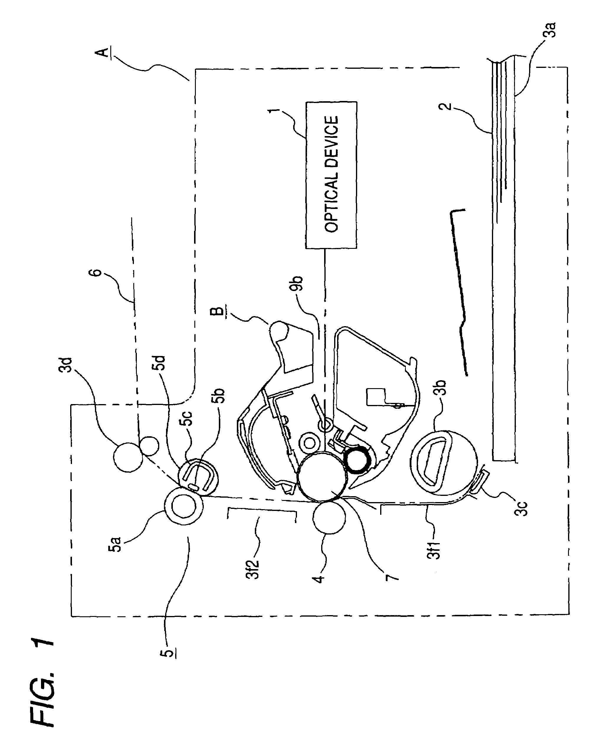
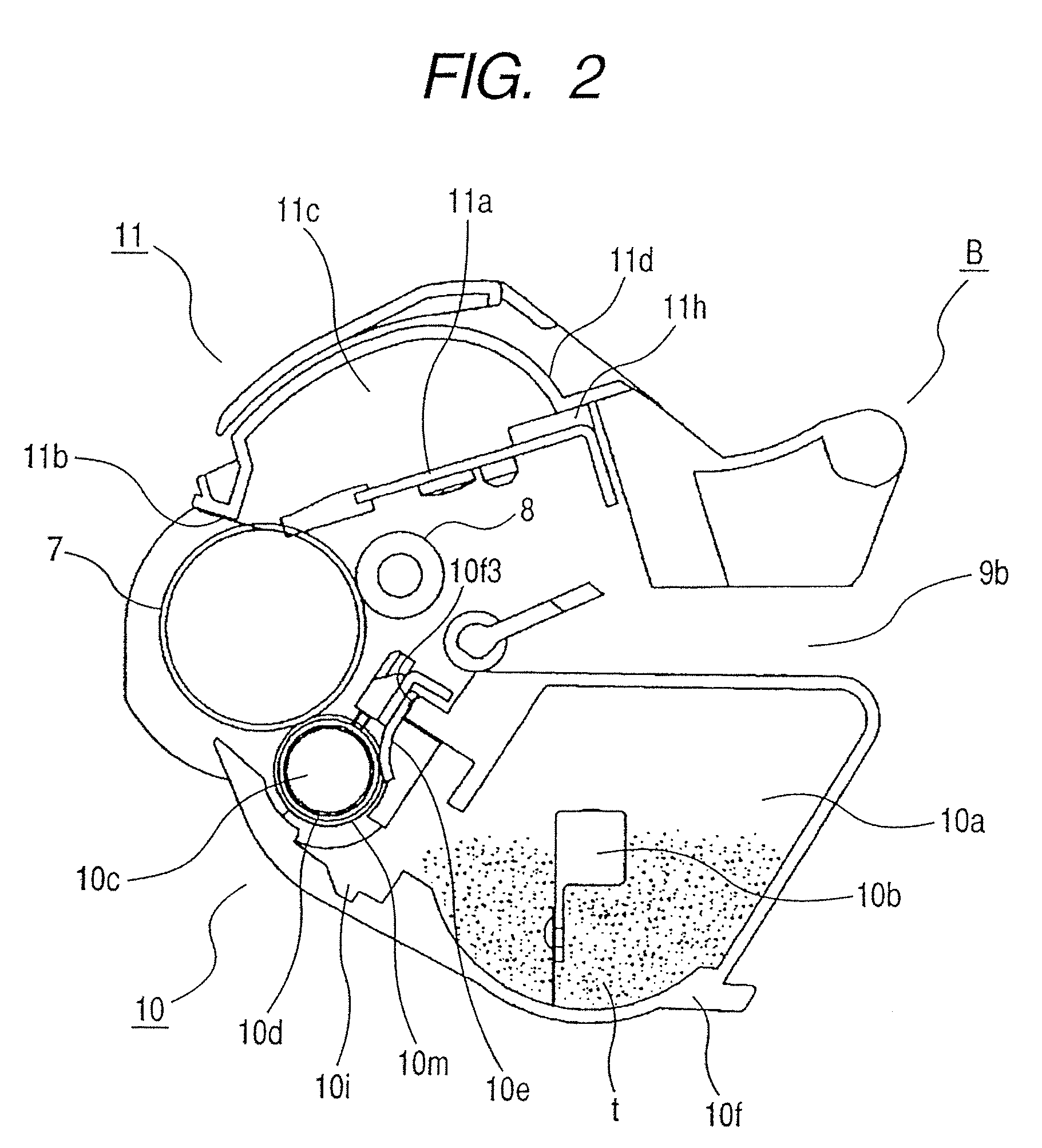
[0034]Reference is first had to FIGS. 1 and 2 to describe a process cartridge and an electrophotographic image forming apparatus to which it is detachably mountable. FIG. 1 is a cross-sectional view showing the construction of an electrophotographic image forming apparatus on which a process cartridge according to the present embodiment is mounted. FIG. 2 is a cross-sectional view showing the construction of a process cartridge according to the present embodiment.

(Electrophotographic Image Forming Apparatus)

[0035]As shown in FIG. 1, the electrophotographic image forming apparatus (a laser beam printer, hereinafter referred to as the “image forming apparatus”) A applies light based on image information from an optical device 1 to a drum-shaped electrophotographic photosensitive member (hereinafter referred to as the “photosensitive drum”) 7. Thereby, an electrostatic latent image is formed on the photosensitive drum 7. Then, this electrostatic latent image is developed with a develop...

second embodiment

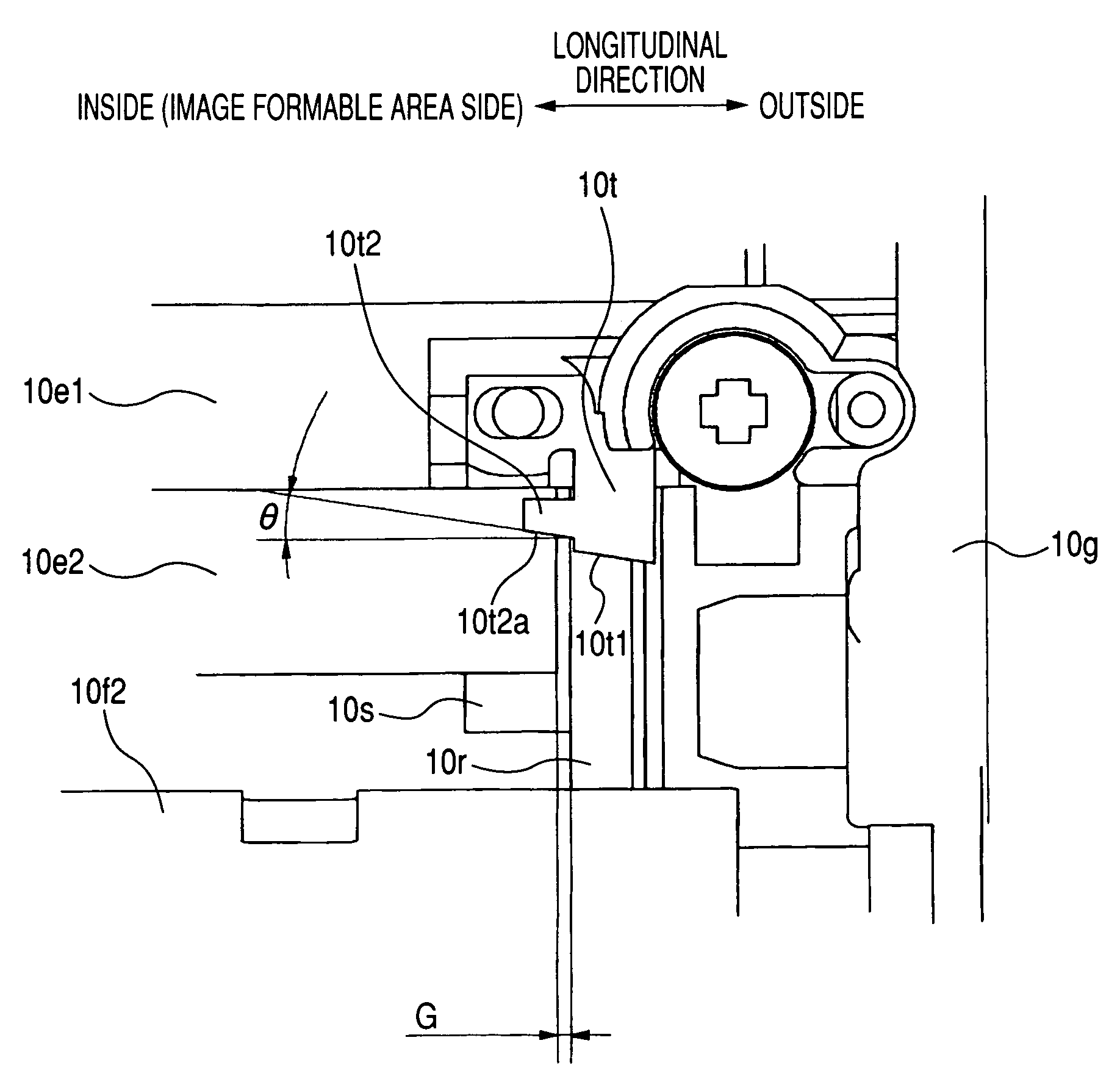
[0070]FIG. 12 is a fragmentary front view of the developing apparatus as it is seen from Y direction in FIG. 8 with end portion regulating members according to a second embodiment and the developing roller mounted on the developing frame member. FIG. 13A is a side view of the end portion regulating member according to the second embodiment, and FIG. 13B is a front view of the end portion regulating member. FIG. 14 is a cross-sectional view of a developing apparatus according to the second embodiment. FIG. 15 is a fragmentary perspective view of the developing apparatus in a state in which the end portion regulating portions according to the second embodiment and the developing roller are mounted on the developing frame member.

[0071]The regulating portion 10t2 according to the present embodiment is of such a shape that in the longitudinal direction of the developing roller 10d, the distance thereof from the developing roller 10d becomes greater from the outside toward the inside (see...

third embodiment

[0075]FIG. 16 is a fragmentary front view of the developing apparatus in a state in which end portion regulating members according to a third embodiment and the developing roller are mounted on the developing frame member. FIG. 17 is a cross-sectional view of a developing apparatus according to the third embodiment.

[0076]In the present embodiment, as end portion seal members, elastic seal members 10r1 such as felt are brought into contact with the developing roller 10d. That is, by the elastic seal members 10r1, the developer “t” is prevented from leaking out from the end portions of the developing roller 10d to the outside of the cartridge B.

[0077]At this time, there may be formed interstices G1 between the rubber portion 10e2 of the developing blade and the seal members 10r1. Therefore, the regulating portions 10t2 are disposed at a distance G3 from the developing roller 10d at a location at which they overlap the interstices G1 in the longitudinal direction. As a result, they reg...


PUM


Abstract

A developing apparatus, a process cartridge and an electrophotographic image forming apparatus which can obtain a good image, and an end portion regulating member provided in them. The end portion regulating members for regulating the layer thickness of developer passed through interstices between a developing blade for forming a layer of the developer having a predetermined thickness on the surface of a developing roller and magnetic seals provided on the longitudinally opposite end portions of the developing roller in opposed relationship with the surface of the developing roller is provided downstream of the developing blade with respect to the rotating direction of the developing roller.

Description

BACKGROUND OF THE INVENTION[0001]1. Field of the Invention[0002]The invention relates to a developing apparatus, a process cartridge, an electrophotographic image forming apparatus and an end portion regulating member.[0003]2. Description of Related Art[0004]Heretofore, a process cartridge system has been adopted in an electrophotographic image forming apparatus using an electrophotographic image forming process. This process cartridge system refers to a system whereby an electrophotographic photosensitive member and process means acting on the electrophotographic photosensitive member are integrally made into a cartridge, which is made detachable mountable to a main body of an image forming apparatus. According to this process cartridge system, the maintenance of the apparatus can be done by an operator himself without resort to a serviceman. Therefore the operability of the apparatus can be markedly improved. So, this process cartridge system is widely used in electrophotographic ...

Claims


Application Information

Patent Timeline
Patent Type & Authority Patents(United States)
IPC IPC(8): G03G15/09G03G15/08
CPCG03G15/0942G03G15/0817
Inventor MORIOKA, MASANARIBATORI, YOSHIYUKIOGINO, HIROKI
Owner CANON KK
Why Eureka
Try Eureka