Braking device for a motor vehicle

a technology for braking devices and motor vehicles, which is applied to vehicle components, brake systems, and brake components, etc., can solve the problems of small displacement and run the risk of disturbing and worrying the driver, and achieve the effect of simple, effective and inexpensiv

Inactive Publication Date: 2008-09-02
ROBERT BOSCH GMBH
View PDF7 Cites 7 Cited by
  • Summary
  • Abstract
  • Description
  • Claims
  • Application Information

AI Technical Summary

Benefits of technology

[0005]The object of the invention is to provide a simple, effective and inexpensive solution to this problem.
[0007]In the braking device according to the invention, the travel simulator may be operated in a simple and reliable manner using inexpensive means each time that the second brake circuit is activated. If the driver then presses on the brake pedal, he then experiences approximately the same sensations as in the case in which the first brake circuit is actuated, and he is therefore not disturbed.

Problems solved by technology

Because the pressure in the second brake circuit is high, any action by the driver on the brake pedal will result in a very small displacement, one which is very unusual for this pedal and which runs a risk of disturbing and worrying the driver.

Method used


Image

  • Braking device for a motor vehicle
  • Braking device for a motor vehicle
  • Braking device for a motor vehicle

Examples


Embodiment Construction

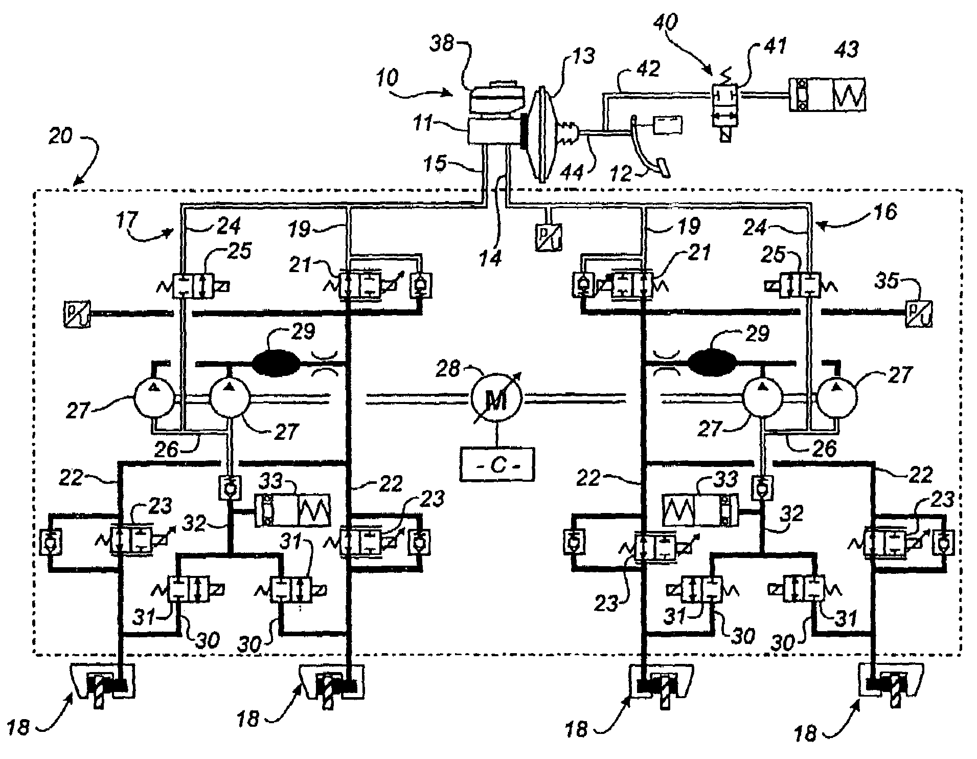
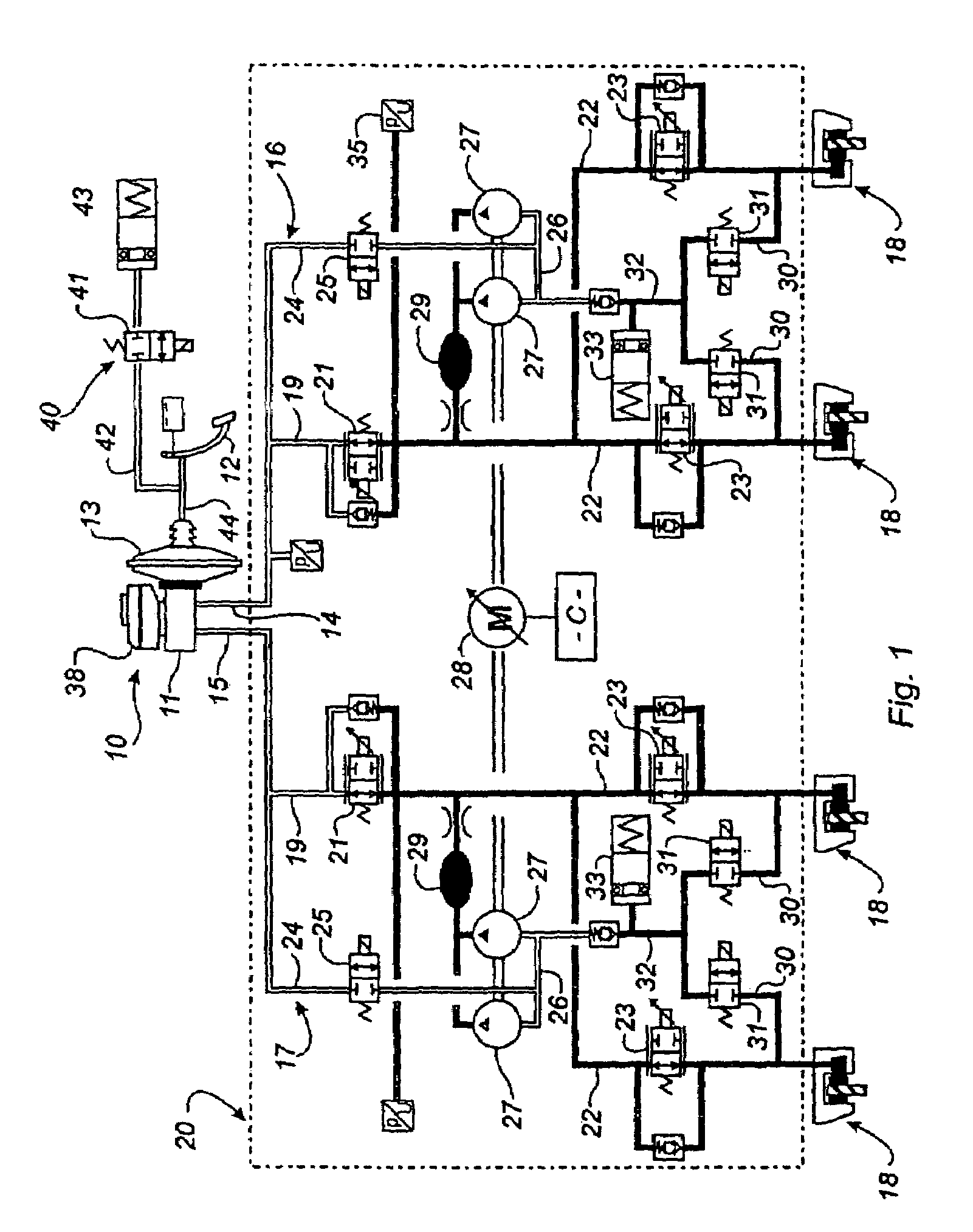
[0019]Referring firstly to FIGS. 1 and 2, these show schematically a first embodiment of a braking device according to the invention.

[0020]This braking device comprises a first brake circuit 10 controlled by the driver of the vehicle and a second brake circuit 20 of the electrohydraulic type, which second brake circuit is controlled by a programmed computer C and the electrical connections of which, for connection to various elements of the braking device, have not been shown in order to simplify the drawing and to make it easier to understand.

[0021]The first brake circuit 10 includes a master cylinder 11, such as a tandem master cylinder, controlled from a brake pedal 12 actuated by the driver of the vehicle, the brake pedal 12 being connected via a control rod to a brake booster 13 in a manner known to those skilled in the art.

[0022]The tandem master cylinder 11 comprises a primary chamber and a secondary chamber, the outlets 14, 15 of which are connected via circuits 16, 17 to br...


PUM


Abstract

A braking device for a motor vehicle having a first brake circuit (10) with a master cylinder (11) controlled by a brake pedal (12), a second brake circuit (20) with at least one pump (27) that is controlled by a computer (C), and a pedal travel simulation mechanism (40). The simulation mechanism (40) includes a solenoid valve (41) that is mounted in a pipe (42) connected to a hydraulic fluid storage chamber (43) and controlled by the computer (C) so as to allow the brake fluid to flow toward the chamber (43) when the second brake circuit (20) is active and when the driver presses on the brake pedal. The pipe (42) is also connected to another pipe (44) in which hydraulic fluid is displaced by a first part (45) of a control rod connected to the brake pedal (12) and second part (46) associated with the master cylinder (11).

Description

BACKGROUND OF THE INVENTION[0001]The invention relates to a braking device for a motor vehicle, comprising a first brake circuit, controlled by the driver of the vehicle, and a second brake circuit controlled by a programmed computer.[0002]The first brake circuit includes a master cylinder controlled in general by a brake pedal, via a pneumatic brake booster, and the second brake circuit includes at least one pump driven by an electric motor and supplied with brake fluid from the master cylinder. The outlet pipes of the master cylinder and of the aforementioned pump are connected to wheel brakes via circuits that include solenoid valves controlled by the computer.[0003]In normal operation, the solenoid valves that connect the outlets of the master cylinder to the wheel brakes are opened by the computer and the wheel brakes are supplied with pressurized brake fluid by the master cylinder of the first brake circuit under the control of the driver when he presses on the brake pedal. Du...

Claims


Application Information

Patent Timeline
Patent Type & Authority Patents(United States)
IPC IPC(8): B60T8/34B60T8/44B60T8/48
CPCB60T8/4872B60T8/4086
Inventor MARLHE, NICOLASLEBOUBE, CHRISTOPHEDURAND, ETIENNEPIEL, JEAN-MARC
Owner ROBERT BOSCH GMBH
Why Eureka
Try Eureka