Low noise phase locked loop with a high precision lock detector

a phase lock and detector technology, applied in the direction of electrical equipment, automatic control, pulse, etc., can solve the problems of notorious noise of conventional pll systems during acquisition and tracking cycles, and achieve the effect of reducing the overshoot of the second voltage tuning signal

Active Publication Date: 2008-09-02
HARRIS GLOBAL COMM INC
View PDF4 Cites 6 Cited by
  • Summary
  • Abstract
  • Description
  • Claims
  • Application Information

AI Technical Summary

Benefits of technology

[0007]A filter network is coupled between the first and second PFDs and the VCO for filtering the first and second voltage tuning signals prior to controlling the frequency of the VCO output signal. The filter network includes resistive and capacitive elements for damping or reducing overshoot of the second voltage tuning signal.

Problems solved by technology

Conventional PLL systems are notoriously noisy during their acquisition and tracking cycles because of the desire to adjust and correct quickly the frequency of the VCO output signal.

Method used


Image

  • Low noise phase locked loop with a high precision lock detector
  • Low noise phase locked loop with a high precision lock detector
  • Low noise phase locked loop with a high precision lock detector

Examples


Embodiment Construction

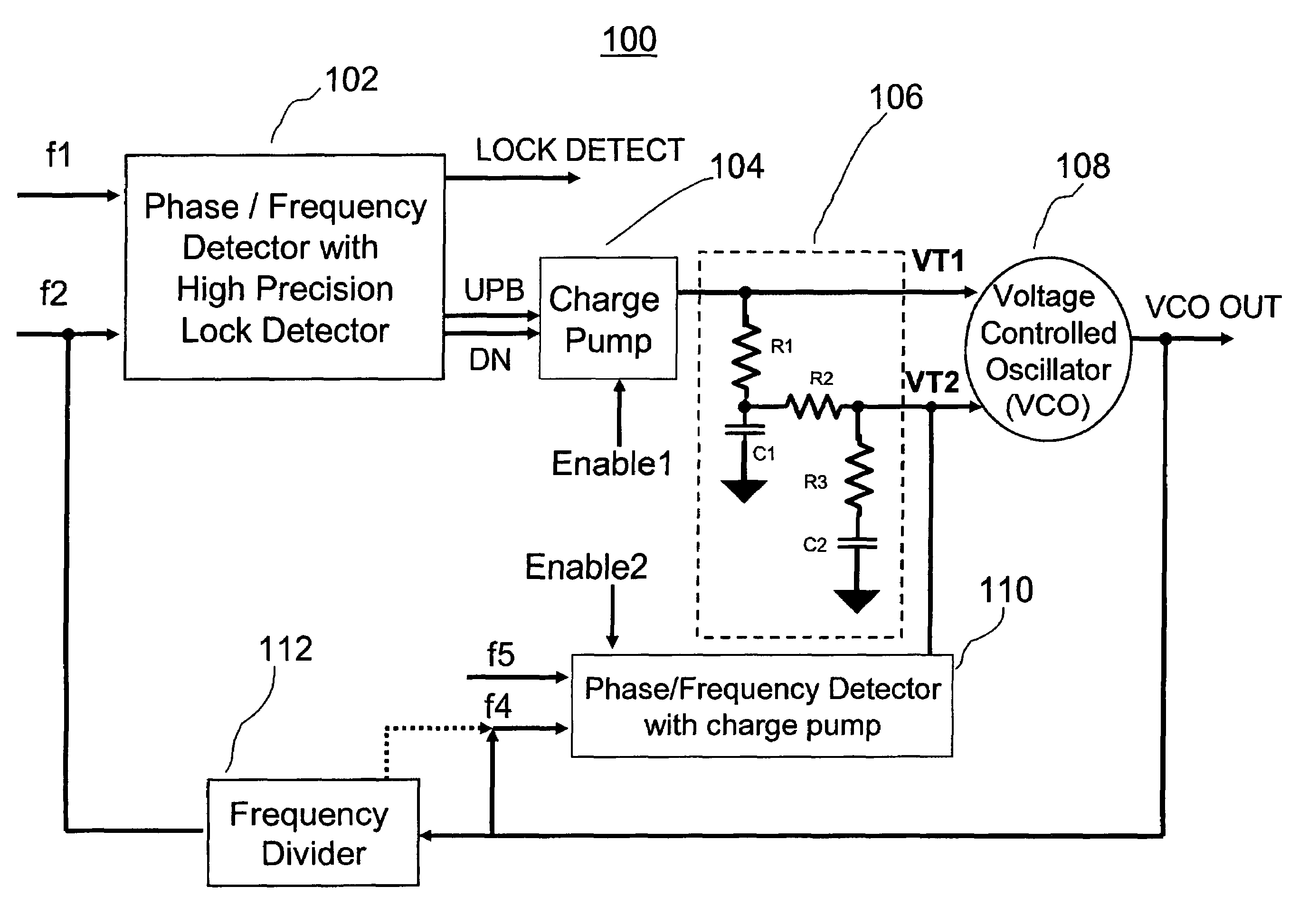
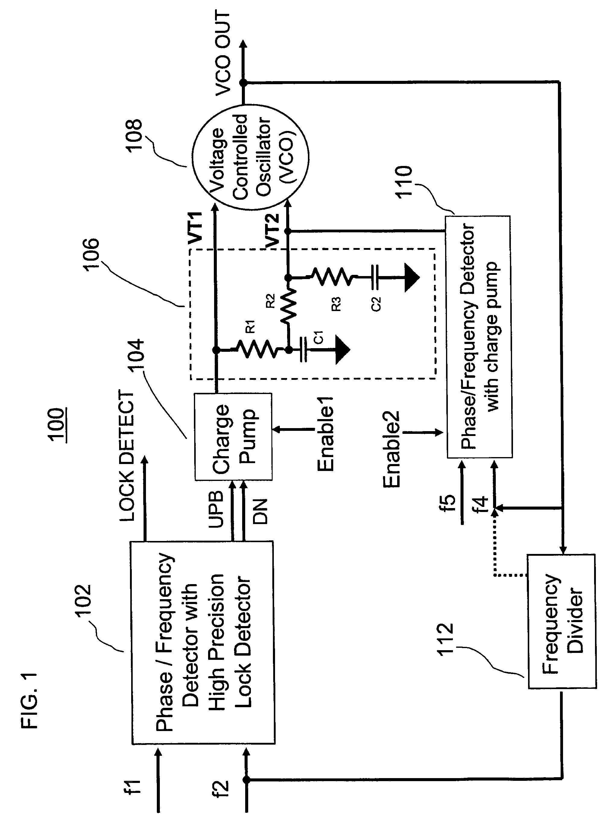
[0026]As will be described, the present invention provides a low noise phase locked loop (PLL) with a high precision lock detector. The PLL includes a voltage controlled oscillator (VCO) that is tuned by two separate tuning signals. The first tuning signal controls the VCO during its acquisition mode and the second tuning signal controls the VCO during its tracking mode. A first phase / frequency detector (PFD) operating a charge pump establishes the first tuning signal. A second phase / frequency detector (PFD) operating a second charge pump establishes the second tuning signal. The first charge pump is enabled during the acquisition mode of the VCO and the second charge pump is enabled during the tracking mode of the VCO. When one charge pump is enabled, however, the other charge pump is disabled.

[0027]The first tuning signal has a large gain that, for example, is greater than 1 GHz per volt, while the second tuning signal has a lower gain that, for example, is less than 1 GHz per vol...


PUM


Abstract

A phase lock loop (PLL) includes a voltage controlled oscillator (VCO) for providing a VCO output signal. A first phase / frequency detector (PFD) for providing a first voltage tuning signal is included for controlling a frequency of the VCO output signal by comparing a first reference signal to the VCO output signal. A second phase / frequency detector (PFD) for providing a second voltage tuning signal is included for controlling the frequency of the VCO output signal by comparing a second reference signal to the VCO output signal. The first and second voltage tuning signals provide, respectively, first and second gains of frequency per volt for controlling the frequency of the VCO output signal. The first voltage tuning signal has a higher gain than the second voltage tuning signal. The first voltage tuning signal provides coarse frequency control of the VCO output signal and the second voltage tuning signal provides fine frequency control of the VCO output signal.

Description

FIELD OF THE INVENTION[0001]The present invention relates, in general, to phase locked loop (PLL) systems. More specifically, the present invention relates to a low noise PLL with a high precision lock detector.BACKGROUND OF THE INVENTION[0002]A phase locked loop (PLL) is a frequency feedback circuit that is used to lock a locally generated clock signal to an external reference signal. A PLL is useful in telecommunications equipment and audio / visual equipment that receive a reference signal and require a local clock signal, whose frequency and phase are related (locked) to the received signal, in order to properly decode incoming signals.[0003]In general, a PLL includes a reference frequency generator, a phase and frequency detector (PFD), a charge pump and a voltage controlled oscillator (VCO). The PFD detects the frequency and phase difference between the VCO output frequency (as a feedback signal) and the reference frequency. The PFD outputs a control signal to the charge pump to...

Claims


Application Information

Patent Timeline
Patent Type & Authority Patents(United States)
IPC IPC(8): H03L7/00
CPCH03L7/087H03L7/0891H03L7/14H03L7/095H03L2207/06
Inventor PERA, FLORINWHITTAKER, DENNIS
Owner HARRIS GLOBAL COMM INC
Why Eureka
Try Eureka