Borescope comprising fluid supply system

a fluid supply system and borescope technology, applied in the field of insertion tube remote viewing devices, can solve problems such as the failure of present borescopes in specialized operating environments, and achieve the effects of reducing heat entry, reducing temperature loss, and preventing heat entry

Inactive Publication Date: 2008-09-09
GE INSPECTION TECH LP
View PDF118 Cites 26 Cited by
  • Summary
  • Abstract
  • Description
  • Claims
  • Application Information

AI Technical Summary

Benefits of technology

[0008]The insertion tube of the borescope can be configured to minimize temperature losses by way of temperature conduction along a surface of the insertion tube. In one example of the invention, the insertion tube includes a multilayer insulation layer assembly including a mesh fiberglass layer interposed between two sealing nonporous polytetrafluoroethylene layers. The inclusion of thermally insulative material in the insertion tube, such as a layer having the thermal conductivity of less than 0.50 BTU-in / (hr-ft / (hr-ft2-F.°) reduces the entry of heat into the borescope through the insertion tube.
[0010]An insertion tube according to the invention can have a light reflective outer surface which reflects energy to further discourage the entering of heat into the insertion tube.

Problems solved by technology

While several types of borescopes have been proposed, present borescopes have been observed to fail in specialized operating environments such as high temperature, high pressure, and liquid operating environments.

Method used


Image

  • Borescope comprising fluid supply system
  • Borescope comprising fluid supply system
  • Borescope comprising fluid supply system

Examples


Embodiment Construction

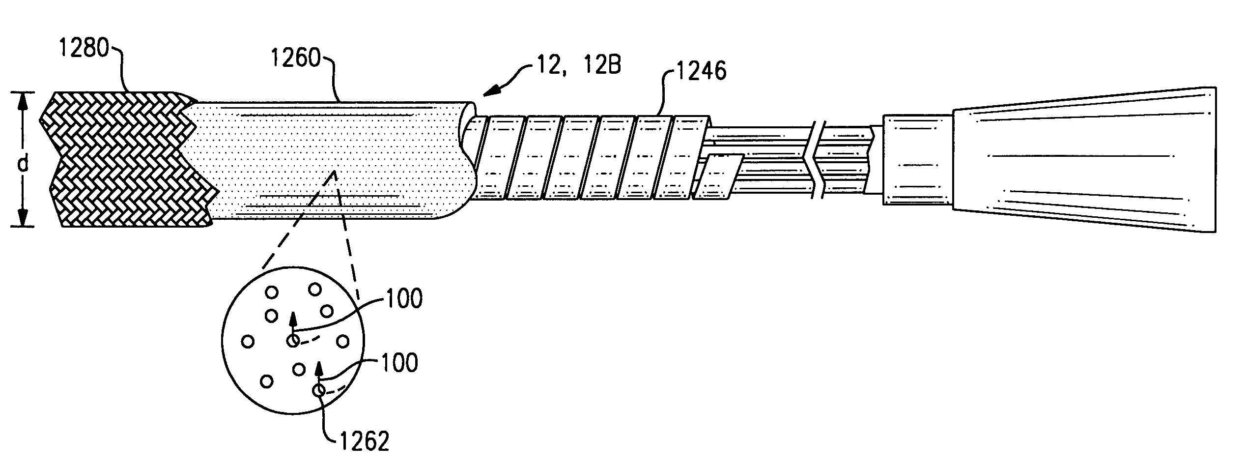
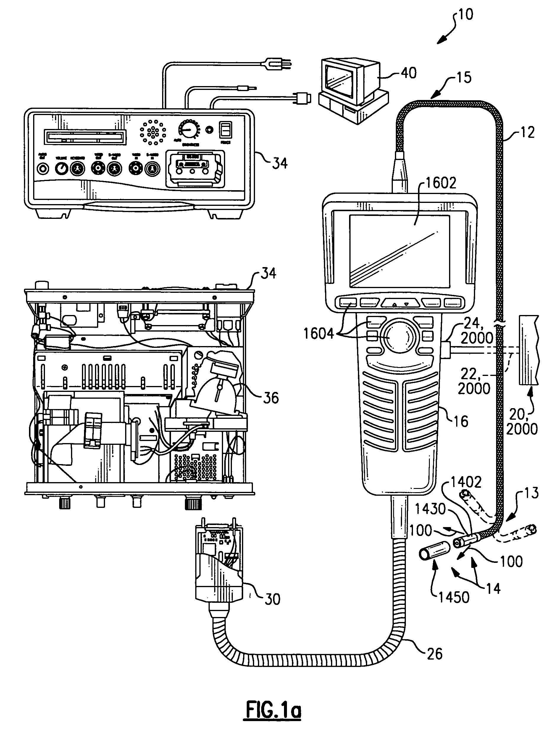
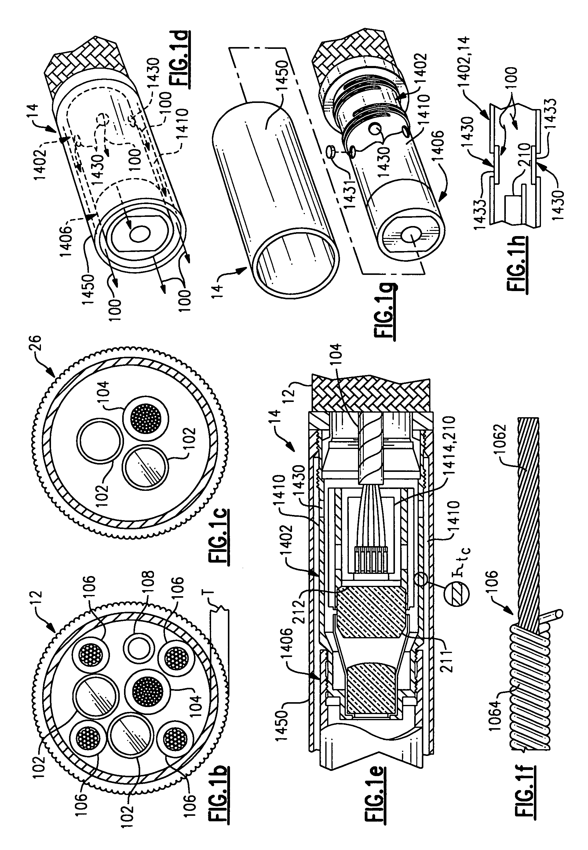
[0025]A borescope 10, according to the invention, is shown in FIG. 1a. Borescope 10 includes flexible insertion tube 12, a camera head assembly 14, and hand piece 16. In accordance with the invention, fluid indicated by flow vectors 100 is forced down a length of insertion tube 12 and flows outwardly about head 1402 of camera head assembly 14 as indicated by fluid flow vectors 100 to cool electrical components of head assembly 14, improving reliability and consistency of performance of the electrical components. Fluid is conveniently supplied to borescope 10 by a fluid supply 20 which, through feed tube 22, is interfaced to connector 24 of hand piece 16. When attached, fluid supply 20, feed tube 22, and connector 24 may be considered part of borescope 10. As will be explained further herein, connector 24 may include a valve 1624 (FIG. 2) for use in regulating the flow of fluid from fluid supply 20. A fluid supply system 2000 of the borescope of FIG. 1a includes fluid supply 20, feed...


PUM

PropertyMeasurementUnit
lengthaaaaaaaaaa
thicknessaaaaaaaaaa
diametersaaaaaaaaaa

Abstract

A borescope device having an insertion tube, a camera head assembly, and a fluid supply system. The camera assembly includes through holes allowing fluid escape. The fluid supply system is controllable to force fluid through the through holes. The fluid supply system may be actuated to cool the camera head assembly.

Description

FIELD OF THE INVENTION[0001]The invention relates to insertion tube remote viewing devices generally and specifically to insertion tube devices configured for use in specialized operating environments.BACKGROUND OF THE PRIOR ART[0002]A borescope is generally characterized as an elongated insertion tube which can be flexible with a viewing head at its distal or forward end. The borescope can also include a control housing at its proximal end for controlling or steering the forward end. Such a borescope has a bendable tube steering section or articulation section at the distal end adjacent to the viewing head. One or two pairs of control articulation cables extend through the articulation section and then through the remainder of the flexible insertion tube. These cables connect with a steering control in the control section. One or both pairs of these cables are differentially displaced to bend the articulation section. The viewing camera head assembly can thus be remotely oriented t...

Claims


Application Information

Patent Timeline
Patent Type & Authority Patents(United States)
IPC IPC(8): A61B1/005G01N21/00H04N7/18A61B1/04A61B1/05A61B1/12G01N21/954G02B23/24
CPCG02B23/2492G01N21/954
Inventor KEHOSKIE, MICHAEL P.KARPEN, THOMAS W.KRAUTER, ALLAN I.LIA, RAYMOND A.MORSE, BRADFORDVON FELTEN, KENNETH
Owner GE INSPECTION TECH LP
Why Eureka
Try Eureka