
Color conversion using barycentric projections

a barycentric projection and color conversion technology, applied in the field of color conversion, can solve the problems of grids (possibly non-uniform sampled), methods are generally slow, and enclosing cells can still be determined quite easily, but not as efficiently,

Active Publication Date: 2008-09-09
CANON KK +1
View PDF15 Cites 15 Cited by
  • Summary
  • Abstract
  • Description
  • Claims
  • Application Information

AI Technical Summary

Benefits of technology

This approach effectively handles complex LUTs, providing a computationally efficient interpolation scheme that can manage scenarios SLI struggles with, ensuring accurate color conversion across various geometrical configurations, including those with incompatible grids and 'gap' situations.

Problems solved by technology

Such methods are generally slow, and are employed only in situations where the sampling locations cannot be arranged.
In the case of non-uniformly sampled rectangular grid, the enclosing cell can still be determined quite easily, though not as efficiently as the uniform case.
An adaptive rectangular grid still employs rectangular grids (possibly non-uniformly sampled) on subspaces, but these grids are not compatible as a whole.
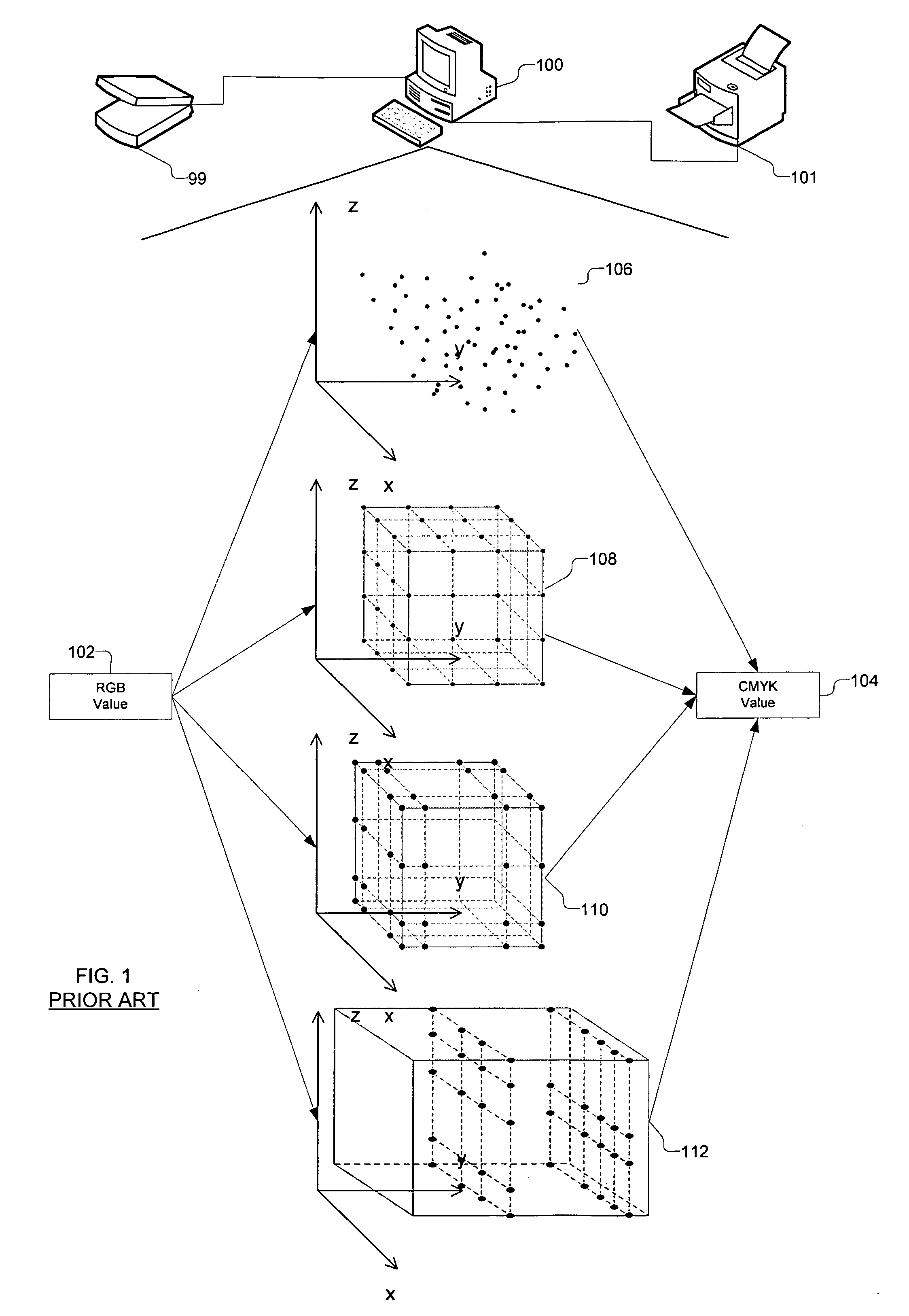
For example, in the standard IT8.7 / 3 target for CMYK printers, sampling on each CMY “plane” for a fixed K is uniform rectangular, but the sampling rate is successively reduced as K increases, because the colors get darker and variations become smaller to make high sampling rate wasteful.
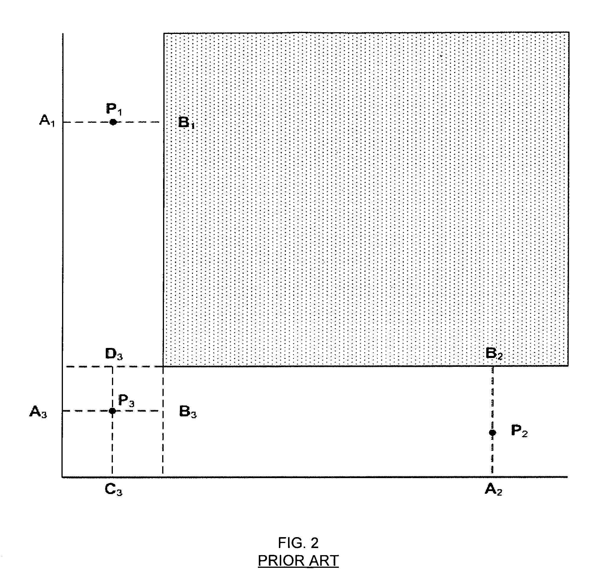
There are other more complicated geometrical situations which SLI cannot handle, or can do so only awkwardly.
One scenario is the “gap interpolation problem” between incompatible grids in different dimensions. FIG. 2 depicts a simple 2-dimensional situation in a x1x2 space where the interior of the space is covered a rectangular grid, and each of the x1 and x2 axis is covered by different 1-D grids, and furthermore these grids are not compatible.
Worst of all, one may get different results from each approach.
Clearly, when the sandwiching geometric objects are more complicated than linear hyperplanes, SLI is not an ideal tool.

Method used


Image

  • Color conversion using barycentric projections
  • Color conversion using barycentric projections
  • Color conversion using barycentric projections

Examples


Embodiment Construction

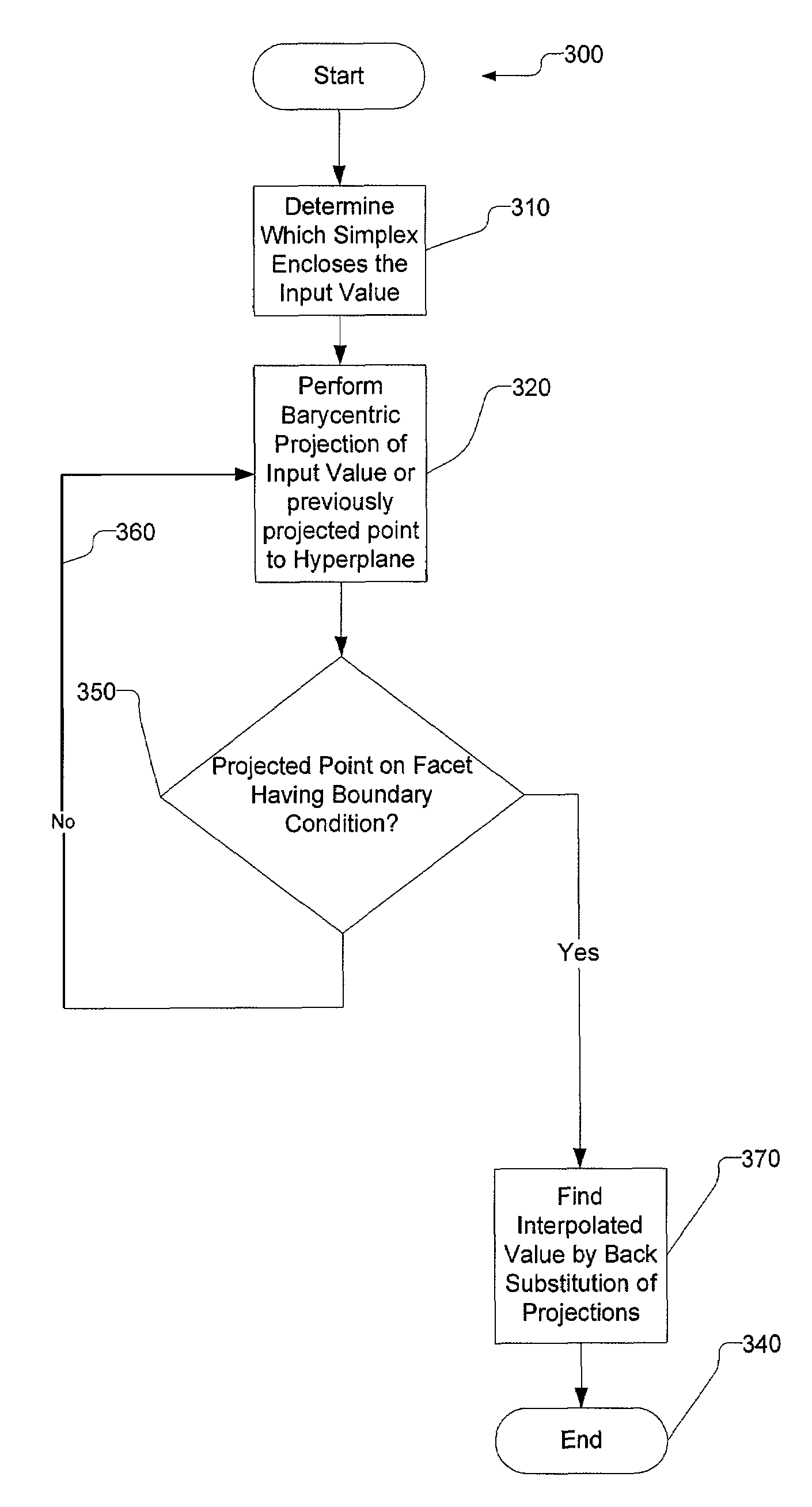
[0032]The present invention is directed to a method of interpolation using LUTs in any arbitrary n-dimensional color space. However, throughout the detailed description, examples are given for 2-dimensional and 3-dimensional spaces, it being understood that the interpolation process may be performed in any n-dimensional color space. Therefore, the following terminology is used in order to identify the types of geometric objects representing the manipulations performed during the interpolation process:[0033]A hypercube is a generalization of a measure polytope, such as a 3-cube, to n dimensions. Hypercubes of lower dimension have specific names. For example, a 1-hypercube is a line segment, a 2-hypercube is a square, a 3-hypercube is a cube, and a 4-hypercube is a tesseract.[0034]A simplex is a generalization of a tetrahedral region of space to n dimensions. The simplex is so-named because it represents the simplest possible polytope in any given space. For example, a 2-simplex is an...


PUM


Abstract

A method and apparatus for interpolating values for a color space from an input color value. A unit hypercube enclosing the input value is generated based on values from a look up table. A set of boundary conditions are then imposed on the unit hypercube. To perform the actual interpolation, an initial barycentric projection is performed from a selected vertex of the unit hypercube through the input value onto a boundary of the unit hypercube. If the projection satisfies one of the boundary conditions, an interpolated value is calculated using the projection by back substitution. If the initial projection does not satisfy a boundary condition, an intermediate value is generated from the previous projection and successive barycentric projections are performed using respectively different vertices of the unit hypercube through intermediate values onto a boundary of the unit hypercube until a projection satisfies one of the boundary conditions.

Description

BACKGROUND[0001]1. Field of the Invention[0002]The present invention relates generally to color conversion and more particularly to color conversion using interpolation of values using look up tables.[0003]2. Description of the Related Art[0004]Electronic imaging systems necessarily involve color space conversions. A system that captures images in Red Green Blue (RGB) space and reproduces them on a Cyan Magenta Yellow blacK (CMYK) printer needs to convert each pixel of the image from RGB space to CMYK space. Also inherent in all but the simplest color space conversion is nonlinearity of the transformation. For example, the RGB to CMYK conversion is usually not a linear transformation. One common technique to handle general nonlinear transformation is through the use of a Look-Up Table (LUT). To generate a LUT, a rectangular grid of nodes is imposed on the source color space and a value in the destination color space is evaluated at each of the nodes. In use, for any color in the sou...

Claims


Application Information

Patent Timeline
Patent Type & Authority Patents(United States)
IPC IPC(8): H04N1/46H04N1/54H04N1/56
CPCH04N1/6022
Inventor TIN, SIU-KEI
Owner CANON KK
Learn More