
Managing headless computer systems

a computer system and headless technology, applied in the field of remote monitoring of computer systems, can solve problems such as uninterruptible power supply and in-band communication channels unavailabl

Inactive Publication Date: 2008-09-09
MICROSOFT TECH LICENSING LLC
View PDF39 Cites 5 Cited by
  • Summary
  • Abstract
  • Description
  • Claims
  • Application Information

AI Technical Summary

Benefits of technology

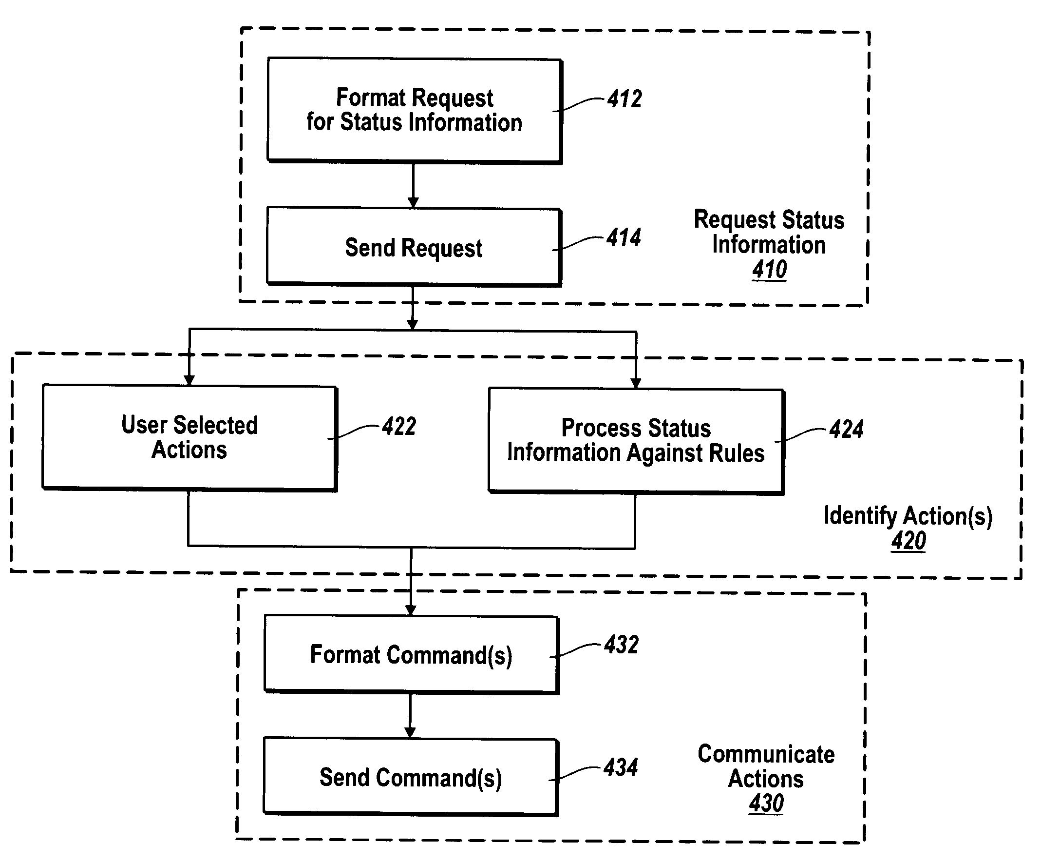
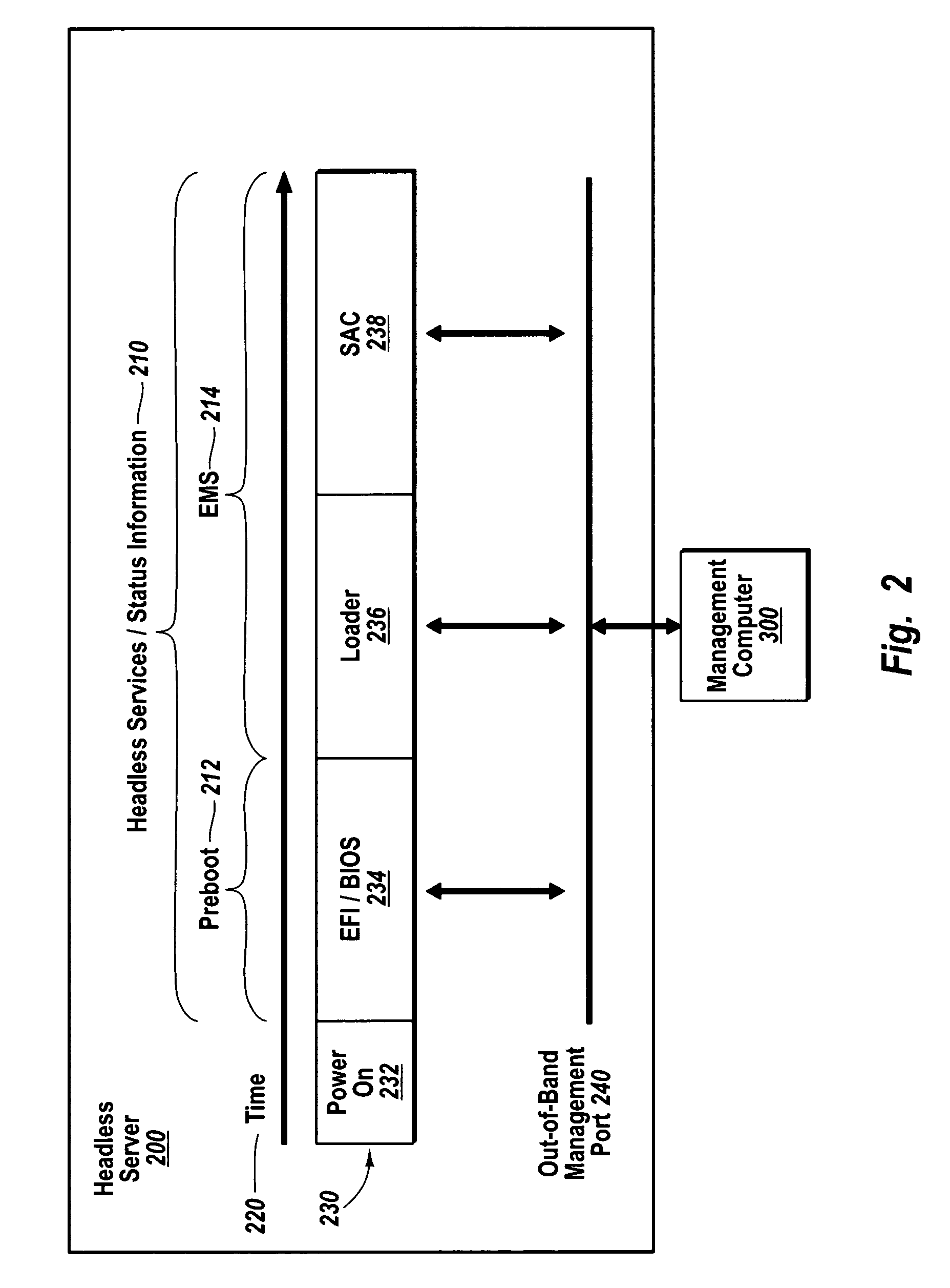
The present invention is about monitoring different computer systems remotely using an out-of-band communication channel. This is useful when the in-band communication channel is unavailable due to hardware or software problems. The management computer system receives status information from the remote computer system through the out-of-band communication channel and identifies actions to take based on the status information. The management computer system can communicate the actions to the remote computer system using the out-of-band communication channel. The remote monitoring can be done using an interactive monitoring application or automated monitoring applications. The invention allows for seamless remote monitoring of different computer systems.

Problems solved by technology

Ordinarily, remote monitoring for these diverse computer systems is performed over an in-band communication channel, but hardware and / or software problems may make the in-band communication channel unavailable for a period of time.
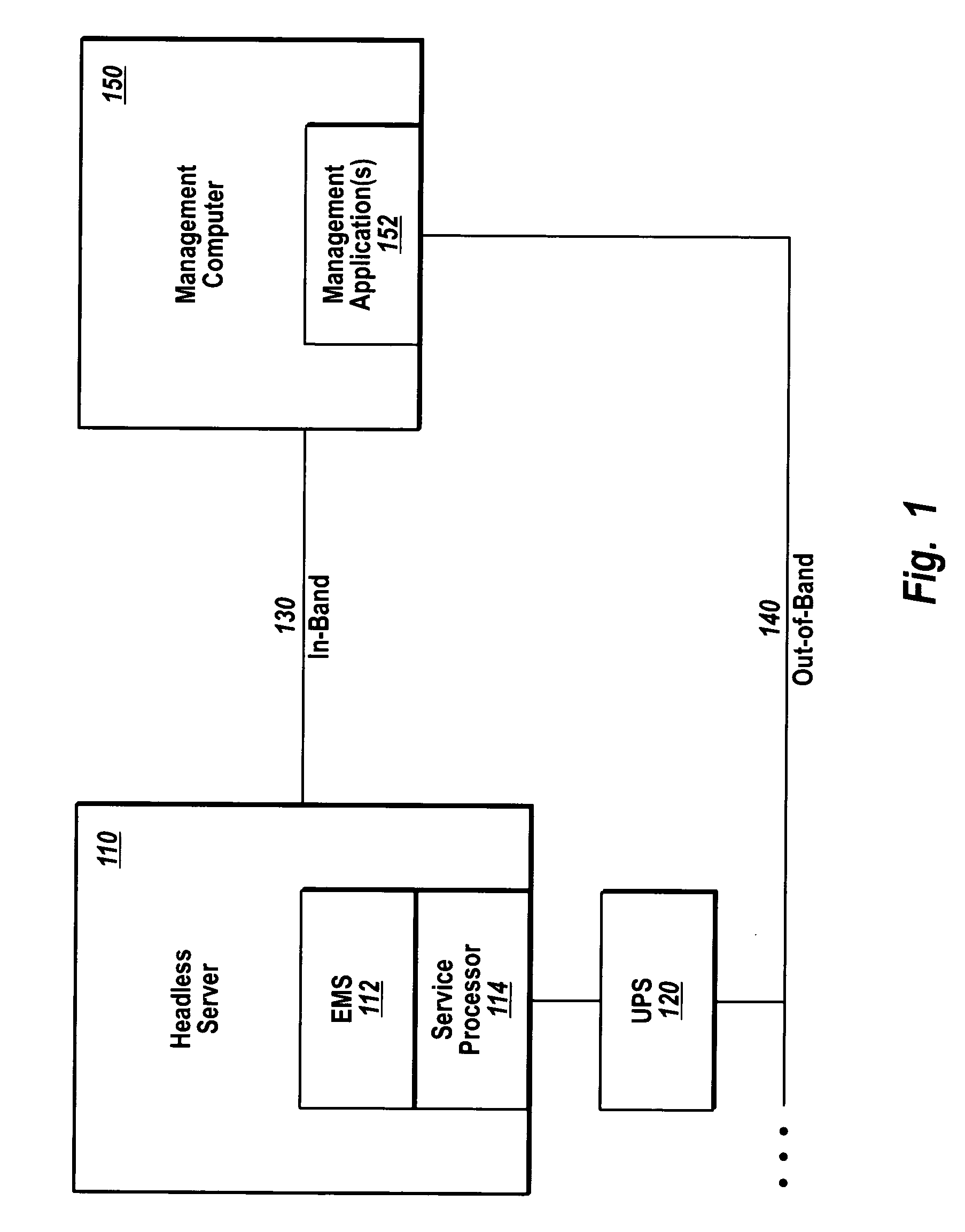
Each diverse computer system may use a variety of hardware to support remote monitoring, including a service processor capable of operating without the headless computer system's operating system and an uninterruptible power supply that can be used to cycle power at the remote computer system.

Method used


Image

  • Managing headless computer systems
  • Managing headless computer systems
  • Managing headless computer systems

Examples


Embodiment Construction

[0022]The present invention extends to methods, systems, and computer program products for remotely monitoring diverse computer systems, in a similar manner, over an out-of-band communication channel. It should be appreciated that remote simply indicates the use of one computer system by another, and does not necessarily imply separation by a significant distance. The embodiments of the present invention may comprise one or more special purpose and / or one or more general purpose computers including various computer hardware and software, as discussed in greater detail below.

[0023]FIG. 1 illustrates an example remote monitoring environment for practicing the present invention. Headless server 110 is a remote computer system that is monitored by management computer 150 over in-band communication channel 130. Headless servers, such as headless server 110 are common in a variety of circumstances where little or no need exists for a monitor, video, keyboard, mouse, etc. For example, head...


PUM


Abstract

Methods, systems, and computer program products for remotely monitoring diverse computer systems in a similar manner over an out-of-band communication channel. Remote monitoring ordinarily is performed over an in-band communication channel. However, hardware and / or software problems may make the in-band communication channel unavailable for a time. While the in-band communication channel is unavailable, the management computer receives status information over the out-of-band communication channel. Based on received status information, the management computer identifies actions to take, such as controlling processes or otherwise configuring the remote computer system, and communicates the actions to the remote computer system over the out-of-band communication channel. The management computer is capable of communicating with any of several diverse computers and exchanges data in a format that is independent of any particular computer system. The format also separates status information from placement information used to display the status information, and may conform to an XML schema.

Description

CROSS-REFERENCE TO RELATED APPLICATIONS[0001]N / ABACKGROUND OF THE INVENTION[0002]1. The Field of the Invention[0003]The present invention relates to remote monitoring of computer systems. More particularly, the present invention relates to methods, systems, and computer program products for remotely monitoring diverse computer systems in a similar manner, over an out-of-band communication channel.[0004]2. Background and Related Art[0005]Remote monitoring of computer systems is desirable for a variety of reasons, including centralization of support personnel, enhanced access to computer systems that are difficult to reach physically, and to reduce space requirements and expenses by allowing for headless systems. For example, computer systems may be located under ground, in cramped closets, on towers or poles, or at distant locations; computer systems may be more densely placed in racks of servers if monitors, video cards, keyboard, mouse, etc. are eliminated; and even for relatively ...

Claims


Application Information

Patent Timeline
Patent Type & Authority Patents(United States)
IPC IPC(8): G06F15/173G06F11/00G06F15/16
CPCG06F11/2294
Inventor GUARRACI, BRIAN J.RITZ, ANDREW J.DEMAIO, PASQUALE
Owner MICROSOFT TECH LICENSING LLC
Learn More