Wire rope pre-failure indicator and method of using same

a pre-failure indicator and wire rope technology, applied in the direction of instruments, apparatus for force/torque/work measurement, ways, etc., can solve the problems of wire rope becoming overstressed, flexible wire rope being exposed to wear and potential damage, catastrophic damage or injury, etc., to achieve convenient swabbing and convenient swabbing

Inactive Publication Date: 2008-09-16
LARSEN STUART +1
View PDF24 Cites 14 Cited by
  • Summary
  • Abstract
  • Description
  • Claims
  • Application Information

AI Technical Summary

Benefits of technology

[0019]With the foregoing in mind it is an object of the present invention to provide a wire rope pre-failure indicating device, which is of a simple, easy-to-use construction, can be installed at any location along a length of conventional wire rope and functions to provide a readily visible pre-failure warning that the wire rope has been loaded beyond a specified magnitude.
[0021]Another object of the invention is to provide a device as described in the preceding paragraphs that includes a viewing portal that enables the status of the device to be conveniently and frequently checked by relatively unskilled observers. More particularly, the viewing portal enables observers to easily see on a real time basis the pre-failure warnings that occur when the wire rope has been loaded beyond a specified magnitude.
[0023]Another object of the invention is to provide a device of the character described in the preceding paragraph in which the body portion of the device is locally work-hardened in order to more accurately control the failure load and to minimize shock-loading of the wire rope during system failure.
[0027]Another object of the invention is to provide a wire rope pre-failure indicating device that includes a conventional eye fitting that can be conveniently swaged on the end of a wire rope.
[0028]Another object of the invention is to provide a wire rope pre-failure indicating device that includes a conventional clevis fitting that can be conveniently swaged on the end of a wire rope.

Problems solved by technology

In many prior art applications, the flexible wire rope is exposed to wear and potential damage as a result of being threaded through various pulleys and sheave configurations and of being wrapped upon and unwrapped from storage drums.
When dynamic tension is applied to the wire rope during any of the aforementioned applications, the wire rope can become overstressed.
If the overstressed condition of the wire rope is not promptly discovered and the situation promptly corrected, the overstressed wire rope will fail resulting in serious and, on occasion, catastrophic damage or injury.

Method used


Image

  • Wire rope pre-failure indicator and method of using same
  • Wire rope pre-failure indicator and method of using same
  • Wire rope pre-failure indicator and method of using same

Examples


Embodiment Construction

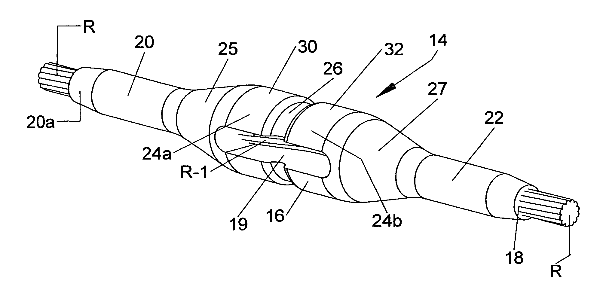
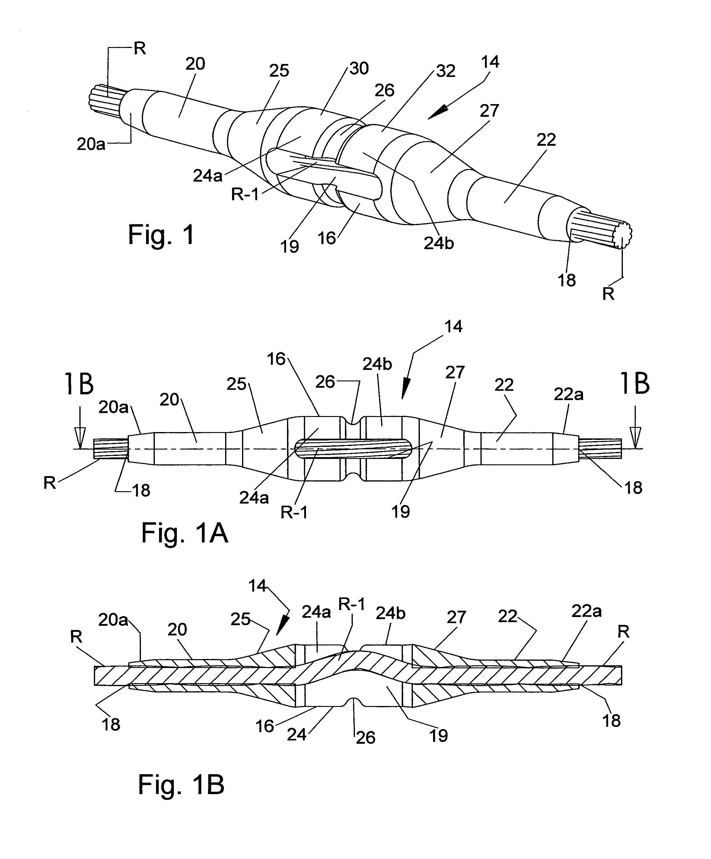
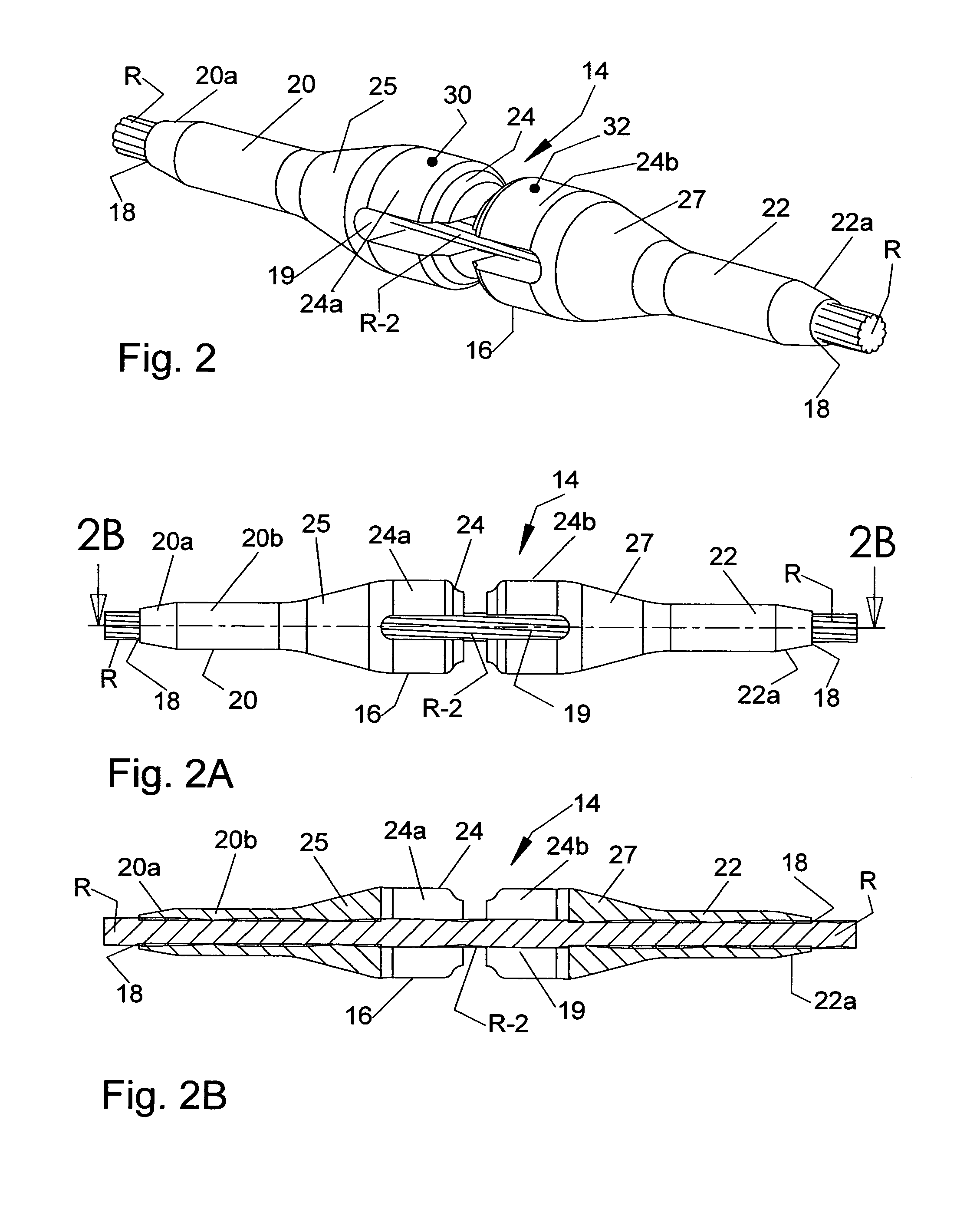
[0047]Referring to the drawings and particularly to FIGS. 1, 1A, 2 and 2A, one form of the pre-failure indicating device of the invention is there shown and generally designated by the 14. The indicating device 14 is specifically designed for use with a length of wire rope “R” that will fail in tension upon applying a load of a first magnitude to the wire rope. In the present form of the invention the indicating device 14 comprises a generally cylindrical casing 16 that surrounds a portion of the wire rope in the manner illustrated in FIGS. 1 and 1B. As shown in FIGS. 1, 1A and 1B, casing 16 is provided with a longitudinal wire rope receiving bore 18 therethrough for receiving the uninterrupted length of wire rope “R”. Additionally, casing 16 is provided with a viewing portal, here shown as a longitudinally extending slot 19, for viewing the length of wire rope. Casing 16 here includes first and second spaced-apart end portions 20 and 22 that are swaged sections connected to the wir...


PUM

PropertyMeasurementUnit
lengthaaaaaaaaaa
lengthaaaaaaaaaa
lengthaaaaaaaaaa

Abstract

A wire rope pre-failure indicating device that can be installed at any location along a length of conventional wire rope of the character used in many industrial applications. The indicating device reliably functions to provide a pre-failure warning that the wire rope has been loaded beyond a specified magnitude. The indicating device also provides a pre-failure warning that the swaged fittings, which interconnect the indicator to the wire rope, have undesirably slipped.

Description

BACKGROUND OF THE INVENTION[0001]1. Field of the Invention[0002]The present invention relates generally to safety devices. More particularly, the invention concerns a wire rope pre-failure indicating device and method of using the same that can be installed at any location along a length of conventional wire rope that provides a pre-failure warning that the wire rope has been loaded beyond a specified magnitude.[0003]2. Discussion of the Prior Art[0004]Flexible wire rope of various sizes is commonly used in various types of industrial applications, including cranes and similar lifting equipment. Wire rope is also extensively used in automotive and aircraft running gear, in marine halyards and in various other types of mechanical control systems.[0005]In many prior art applications, the flexible wire rope is exposed to wear and potential damage as a result of being threaded through various pulleys and sheave configurations and of being wrapped upon and unwrapped from storage drums.[0...

Claims


Application Information

Patent Timeline
Patent Type & Authority Patents(United States)
IPC IPC(8): B21F9/00
CPCG01L5/101Y10T403/11F16B2200/63
Inventor LARSEN, STUARTTURNBULL, WILLIAM
Owner LARSEN STUART
Why Eureka
Try Eureka