Method for correcting butting zone artifacts with an x-ray detector and an x-ray detector

a technology of x-ray detector and butting zone, which is applied in the field of method for correcting butting zone artifacts with an x-ray detector, can solve the problems of loss of image information, unnecessarily large region of peripherally arranged pixels being subject to correction, etc., and achieves the effect of ensuring replacemen

Inactive Publication Date: 2008-09-23
SIEMENS HEALTHCARE GMBH
View PDF9 Cites 3 Cited by
  • Summary
  • Abstract
  • Description
  • Claims
  • Application Information

AI Technical Summary

Benefits of technology

[0012]To implement the correction, the determination of the difference between the first and second gray-scale values as a function of the correction length based on a calibration image and finally the determination of a minimal correction width for each of the measuring fields based on the predetermined parameters and the determined difference are only needed once. A specific correction pattern is thus generated for the detector module, with which correction pattern a minimal correction width is determined as a function of predetermined parameters. The minimal correction width is determined based on predetermined parameters. The proposed method avoids the use of a constant correction width which is selected too large in many cases and thereby a certain loss of image information in the region of the butting zone. The first and second gray-scale values according to the predetermined algorithm can be corrected rapidly and in a simple manner with the generation of an image using the minimal correction width.
[0015]According to a further measure of the invention, provision is made in an x-ray detector for a storage means, in which is stored a table with parameters for the detector-specific correction of butting zone artifacts. The provision of the storage means allows the detector to be operated in a simple manner. It can readily be replaced with another detector. To implement the claimed correction of butting zone artifacts, it is possible to read out the parameters stored in the storage means and to correct the signals according to the claimed method supplied by the detector for correcting butting zone artifacts. The minimal correction widths and the correction lengths corresponding in each instance thereto can be stored in the table as parameters. Furthermore, a further parameter relating to the correction height can be stored in the table in addition to value pairs comprising minimal correction width and correction length corresponding thereto.

Problems solved by technology

Consequently, the pixels in the region of the butting zone supply erroneous signals which effect so-called butting zone artifacts in the image.
This however disadvantageously results in an unnecessarily large region of the peripherally arranged pixels being subject to a correction in the event of weakly developed signal deviations.
This in turn results in a loss of image information.

Method used


Image

  • Method for correcting butting zone artifacts with an x-ray detector and an x-ray detector
  • Method for correcting butting zone artifacts with an x-ray detector and an x-ray detector
  • Method for correcting butting zone artifacts with an x-ray detector and an x-ray detector

Examples


Embodiment Construction

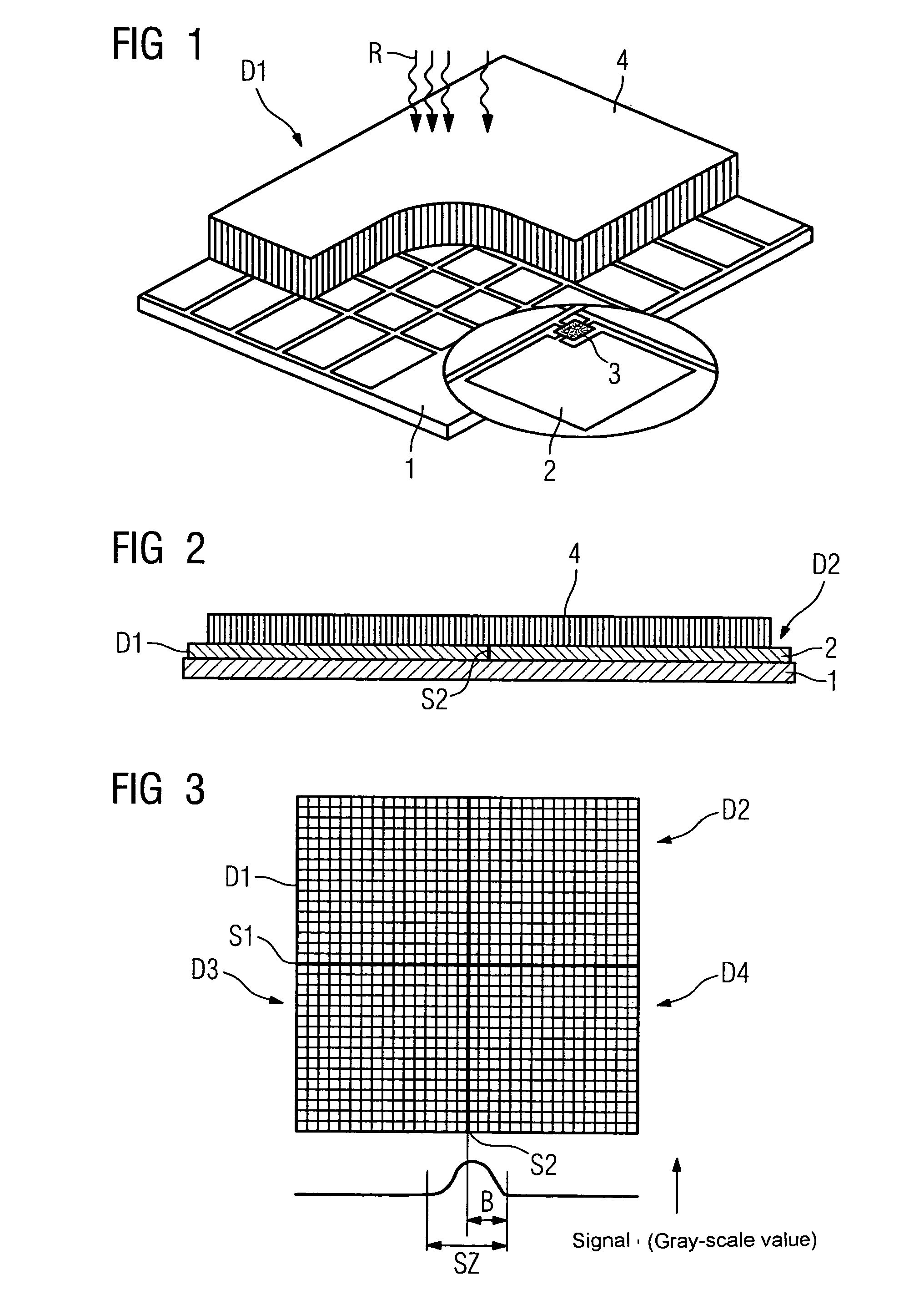
[0022]By way of example, FIG. 1 shows a partially broken perspective view of some essential components of a detector module D1. A plurality of photo diodes 2 are provided on a substrate 1 according to a type of matrix formed from lines and columns. Each of the photo diodes 2 comprises a switch 3, which allows a selective read out of charge signals. A converter layer formed for instance from a scintillator and / or CsI is identified with reference character 4. The converter layer 4 converts incident x-rays R into visible light, which is in turn detected by the photo diodes 2 arranged therebelow.

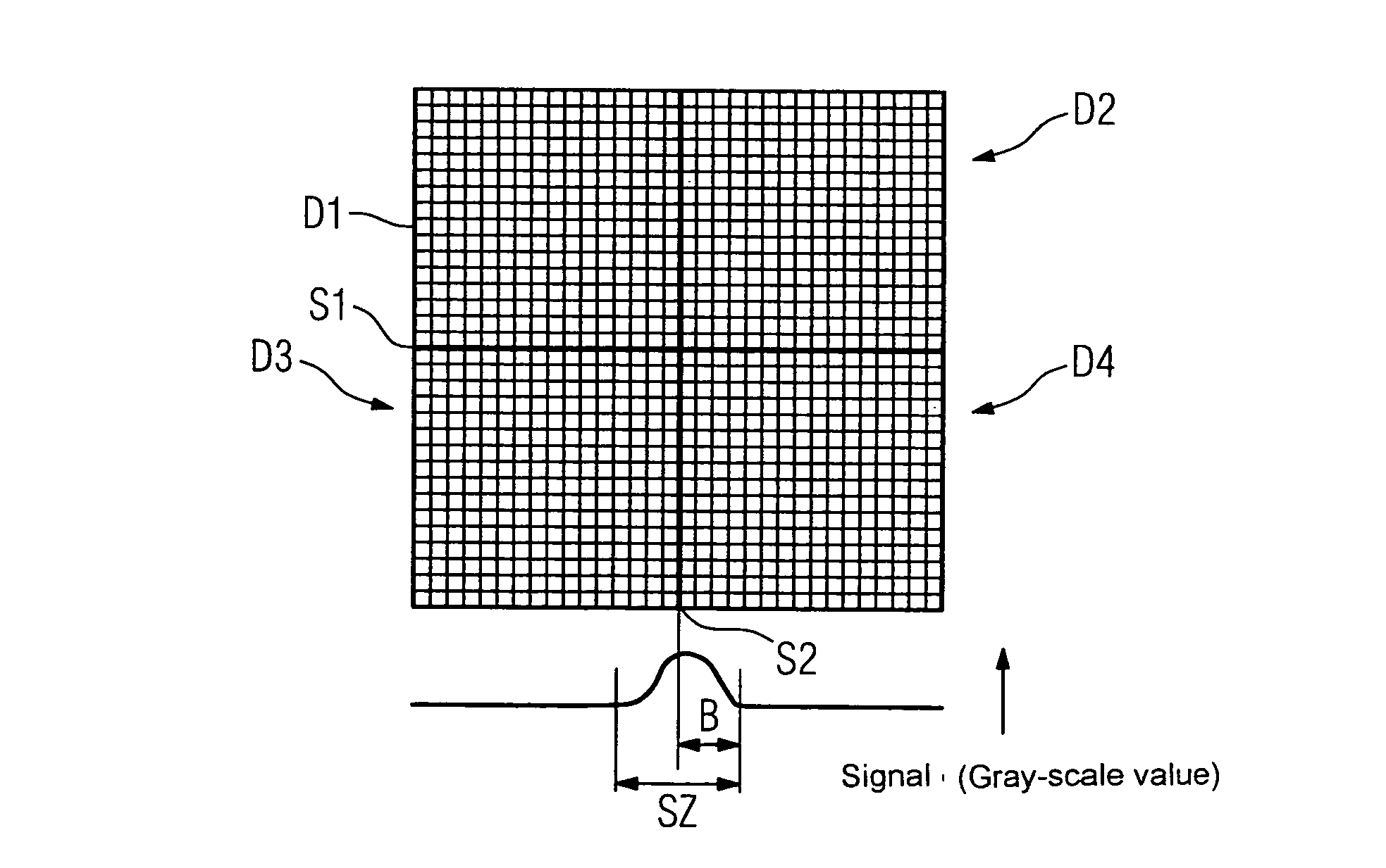
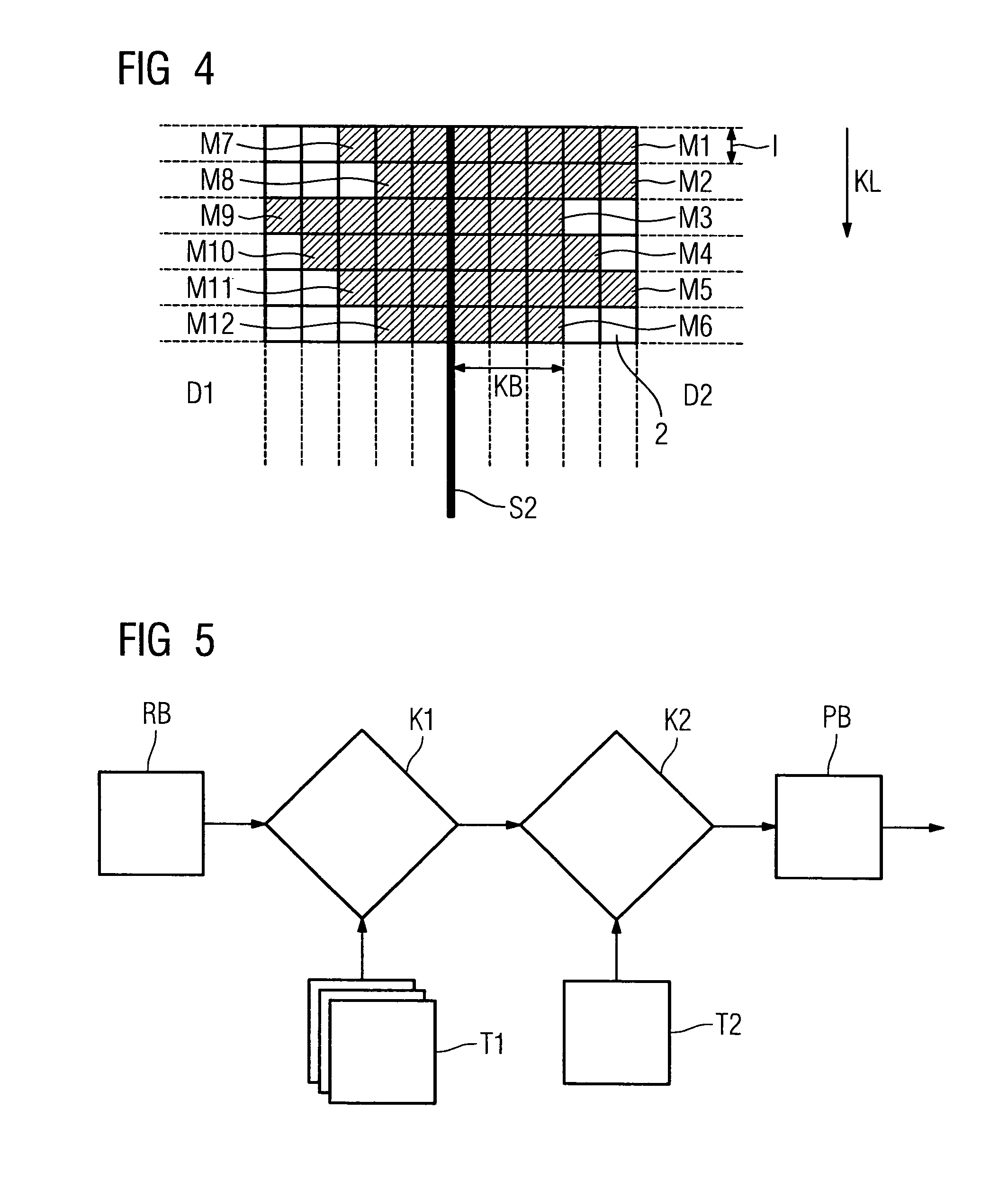
[0023]FIGS. 2 and 3 shows a large area x-ray detector, which is produced from several detector modules D1, D2 and / or D1 to D4 aranged in parallel to the edges. The detector modules D1, . . . ,D4 abut each other along the butting lines S1, S2. The detector modules D1, . . . ,D4 can touch each other in the region of the butting lines S1, S2. FIG. 3 further shows the path of a signal in the region ...


PUM


Abstract

The invention relates to a method for correcting butting zone artifacts with an x-ray detector, which comprises a number of laminar detector modules arranged next to one another by forming a butting zone. To improve a known algorithm, it is proposed to determine a necessary correction width for measuring fields on the basis of a correction image.

Description

CROSS REFERENCE TO RELATED APPLICATIONS[0001]This application claims priority of German application No. 10 2005 032 275.1 filed Jul. 11, 2005, which is incorporated by reference herein in its entirety.FIELD OF THE INVENTION[0002]The invention relates to a method for correcting butting zone artifacts with an x-ray detector. It relates further to an x-ray detector suited to implementing the method.BACKGROUND OF THE INVENTION[0003]Such a method is known from DE 101 35 427 A1. According to the prior art, large-area x-ray detectors comprise several laminar detector modules. The detector modules are usually of a square or rectangular design. To produce a large detector area, the detector modules are assembled in parallel to the edges. A so-called butting zone forms in the region of the edges arranged next to one another, in which butting zone the signal transport characteristics are different to inside the detector module. In the region of the butting zone, the optical characteristics are...

Claims


Application Information

Patent Timeline
Patent Type & Authority Patents(United States)
IPC IPC(8): G01D18/00H04N5/217H04N5/335H04N5/365
CPCH04N5/3653H04N5/32H04N25/672
Inventor SPAHN, MARTIN
Owner SIEMENS HEALTHCARE GMBH
Why Eureka
Try Eureka