System and method for monitoring driver fatigue

a technology for monitoring system and driver, applied in the direction of driver input parameters, electric devices, non-deflectable wheel steering, etc., can solve the problem of diminishing the amount of physical steering, and achieve the effect of low cost, easy maintenance and effectiveness, and cost-effective design

Inactive Publication Date: 2008-09-23
TRIODYNE SAFETY SYST L L C
View PDF12 Cites 51 Cited by
  • Summary
  • Abstract
  • Description
  • Claims
  • Application Information

AI Technical Summary

Benefits of technology

[0010]One important advantage of the system is that driver sleep and / or fatigue is detected within seconds of onset, thereby awakening the driver. This saves lives, community property and cargo.
[0012]The subject invention is intended to be a practical for both pre- and post-production application to vehicles. Standard off-the-shelf automotive components may be used for motion detection and off-the-shelf electronics (programmable logic controllers) were used. This makes the design cost effective and easy to maintain as no special parts must be developed or fabricated. Low cost and easy maintenance and effectiveness usually lead to market acceptance. As for the safety criteria, waking a sleeping driver will prevent accidents or allow the driver opportunity to mitigate them.

Problems solved by technology

Research indicates that as drivers begin to become inattentive or fall asleep, the amount of physical steering they do diminishes.

Method used


Image

  • System and method for monitoring driver fatigue
  • System and method for monitoring driver fatigue
  • System and method for monitoring driver fatigue

Examples


example 1

Cruise Control Deactivation

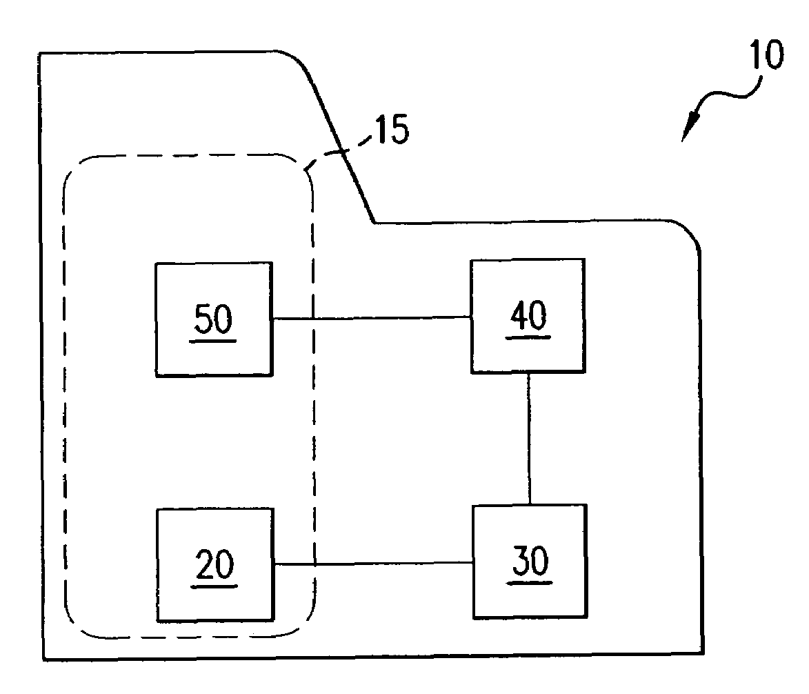
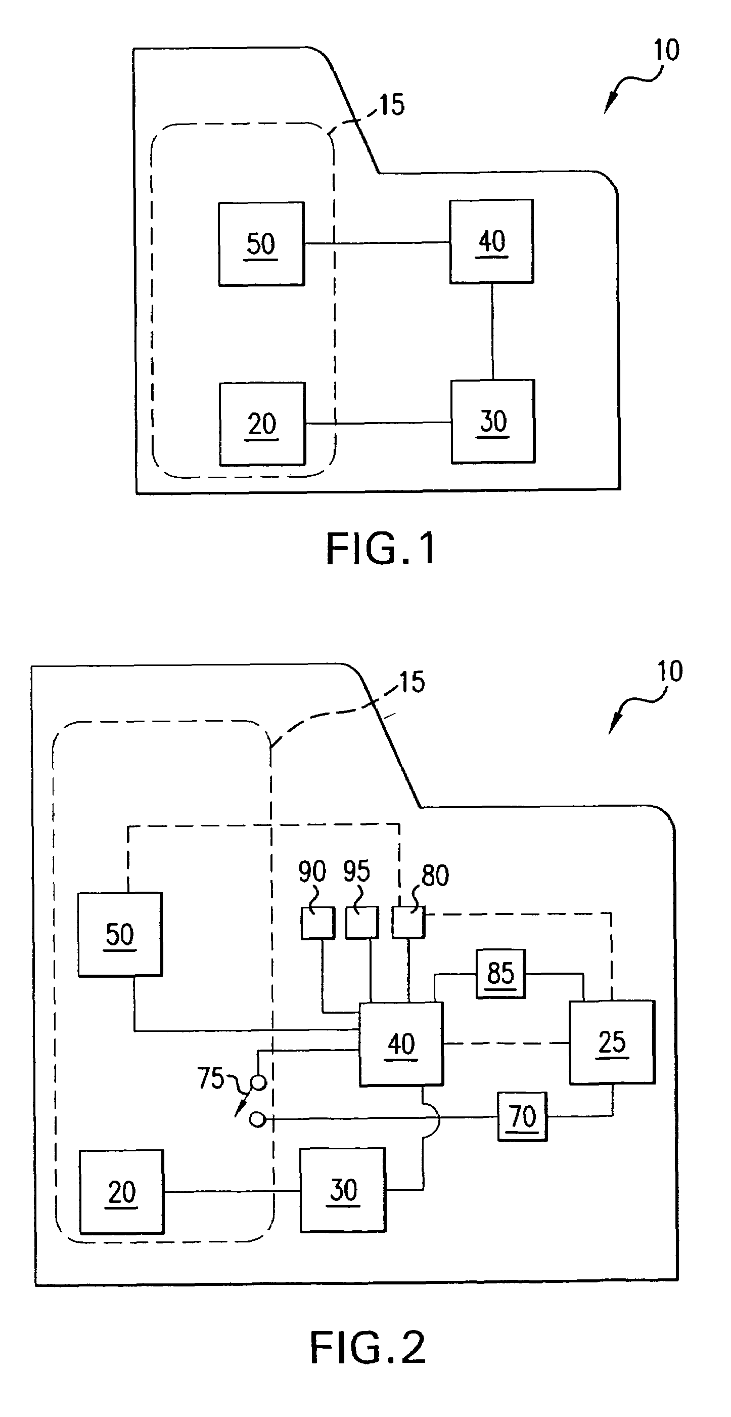
[0043]As described above, the driver fatigue monitoring system may comprise the following components: ABS tone-ring 35, ABS sensor, wiring and a controller 40 consisting of a networked I / O module. The networked I / O module may feature universal input-output ranges and a micro-controller to provide monitoring and control capabilities. This networked I / O module monitors discreet levels of various devices and / or provides on / off control capabilities. The networked I / O module function capability preferably includes control of: on / off; high / low; open / close switching; along with activation of audible and visual alarms.

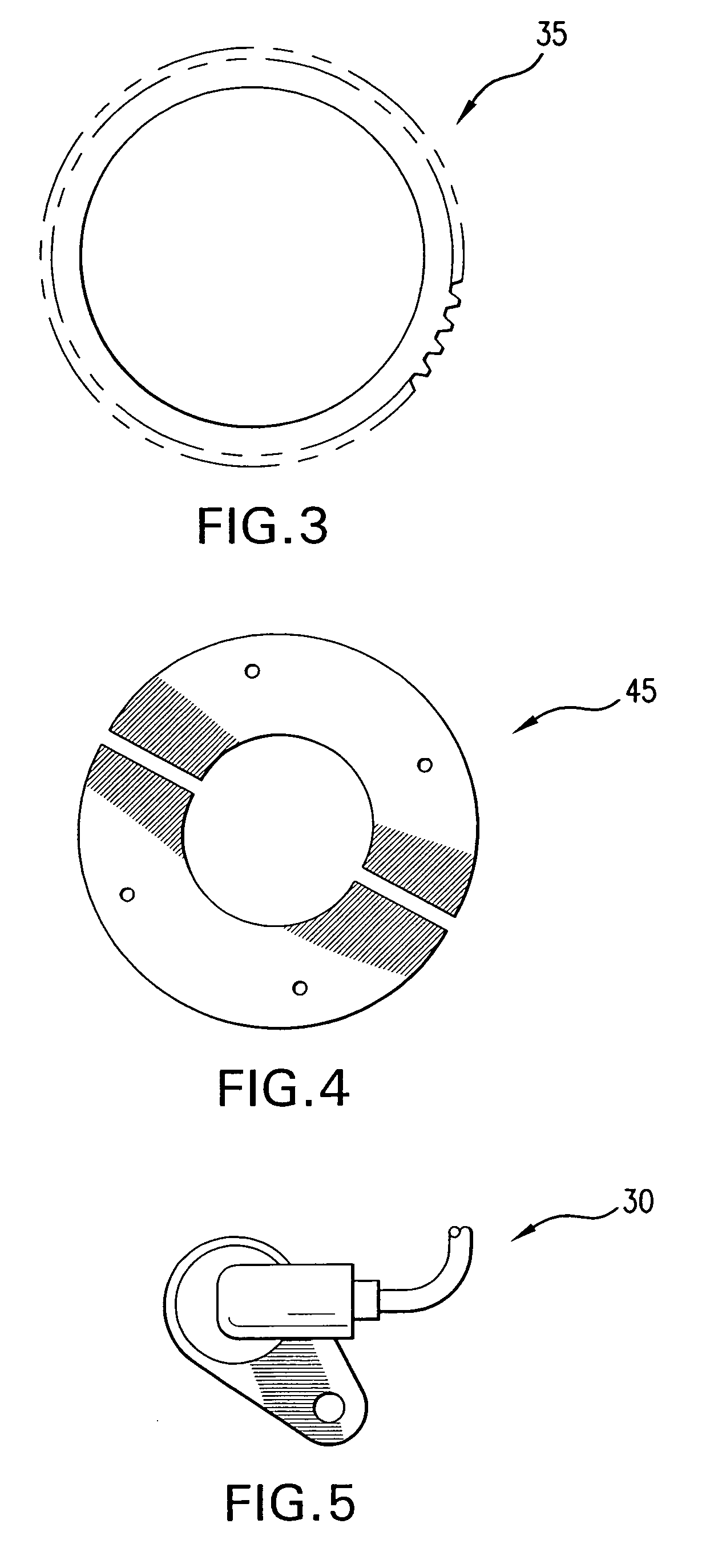
[0044]Tone-ring 35, such as shown in FIG. 3, maybe mounted on steering shaft 22 within an engine compartment of the vehicle or a cab shaft within passenger compartment 15 of the vehicle by way of a self-centering clamp 45, such as shown in FIG. 4. The self-centering clamp 45 permits tone-ring 35 to mount to steering shaft 22 concentrically. Sensor 30...

example 2

Cruise Control Deactivated

[0046]This system may be comprised of components as described above, or alternatively, by non-automotive components with the exception of tone ring 35. An industrial proximity sensor may be used in place of the ABS sensor. The industrial proximity sensor has the ability to actually detect a discreet number of tooth counts from the tone ring, such as shown in FIG. 8.

[0047]The tone ring 35 and proximity sensor preferably operate in a similar manner as the components described in Example 1. However, the signal generated from the proximity sensor is preferably fed into a programmable logic controller (PLC). The PLC preferably uses ladder logic to evaluate the steering input and the subsequent output actions. The PLC is programmed originally through an interface, such as a laptop computer, but can be reprogrammed through a touch pad on its face. As long as the PLC detects a signal (such as 3 pulses in 6 seconds), no action is taken.

[0048]If the signal drops belo...


PUM


Abstract

A method and apparatus for monitoring driver fatigue in a vehicle having a steering control includes connecting a sensor with respect to the steering control and a controller with respect to the sensor. A steering input count signal and / or steering wheel rotation signal is provided from the sensor to the controller and an alarm is activated when the steering input count signal drops below a minimum level and / or the steering wheel rotation signal exceeds a maximum level. The alarm may trigger physical responses within the vehicle including audible, visual, engine management and / or similar responses.

Description

FIELD OF THE INVENTION[0001]This invention relates to a driver monitoring device, system and method for determining and responding to fatigue and / or inattention of the driver.DESCRIPTION OF RELATED ART[0002]The N.T.S.B. has reported statistics which indicate that 31% of all fatal-to-the-truckdriver accidents occur due to fatigue / inattention and 58% of all single-vehicle large truck crashes were also fatigue related. If these numbers can be reduced, so can the number of serious and fatal accidents.[0003]Commercial drivers drive long hours each day and up to 70 hours per week. Such driving occurs throughout all hours of a day: daylight, dusk and night. Fatigue has long been a problem for commercial drivers. Fatigue is cumulative; without proper rest periods, or “off-duty” cycles, fatigue will “accumulate” in the human body and eventually create moments when the driver has to struggle to stay awake. Once this occurs, the overall performance of the driver is greatly compromised.[0004]Th...

Claims


Application Information

Patent Timeline
Patent Type & Authority Patents(United States)
IPC IPC(8): G08B13/00A01B69/00B60K28/00B60K28/10G01F7/00G08B23/00G08B21/00G01M17/00
CPCG08B21/06B60K28/066B60W2540/18
Inventor FERRONE, CHRISTOPHER W.SINKOVITS, CHARLES
Owner TRIODYNE SAFETY SYST L L C
Why Eureka
Try Eureka